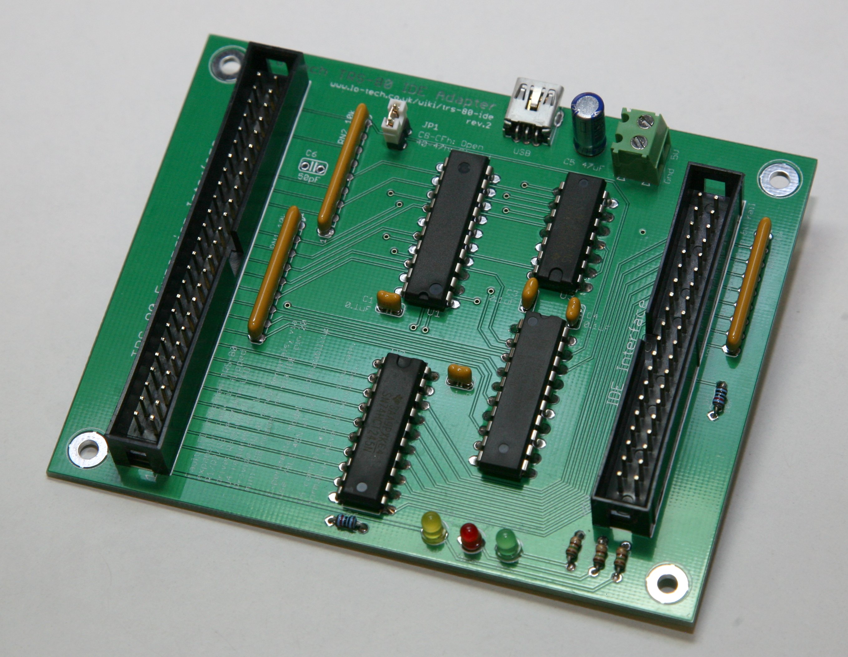
The Lo-tech TRS-80 IDE adapter is an external IDE storage adapter for Tandy TRS-80 model 3/4/4P PCs, enabling connection of standard IDE drives (and CompactFlash cards, with an adapter).
A limitation has been that the machines needed to be booted from floppy disk still, since there is no HDD boot code in the Model 3 and 4 ROMs, and the HDD boot code in the 4P ROM is expecting a WD1010 controller rather than an ATA drive.
Community to the rescue as Audronic, Gazza and Hans have burnt plenty of midnight oil patching the 4P ROM with enough code to get LSDOS 6.3.1 to start up directly from the Lo-tech adapter! Here it is in action:
Currently this has been tested with a number of hard disks (full list in the download) but doesn’t currently work with SD cards. Some DoM devices can though be used, this one having been tested OK. Gazza has kindly put together a RAR achive with the patched ROM binary along with very detailed documentation, which is available via the Lo-tech wiki now.
No more floppy disks needed for your 4P!
Product links have been included here for convenience; Lo-tech has no connection with the sellers.
I’ve been experimenting with 3D printing options for Lo-tech ISA card slot brackets for some time, the idea being for customers ultimately to print their own slot brackets at home as the technology becomes ever more accessible – the XT-CF-lite rev.2 adapter bracket is only currently available in .STL format.
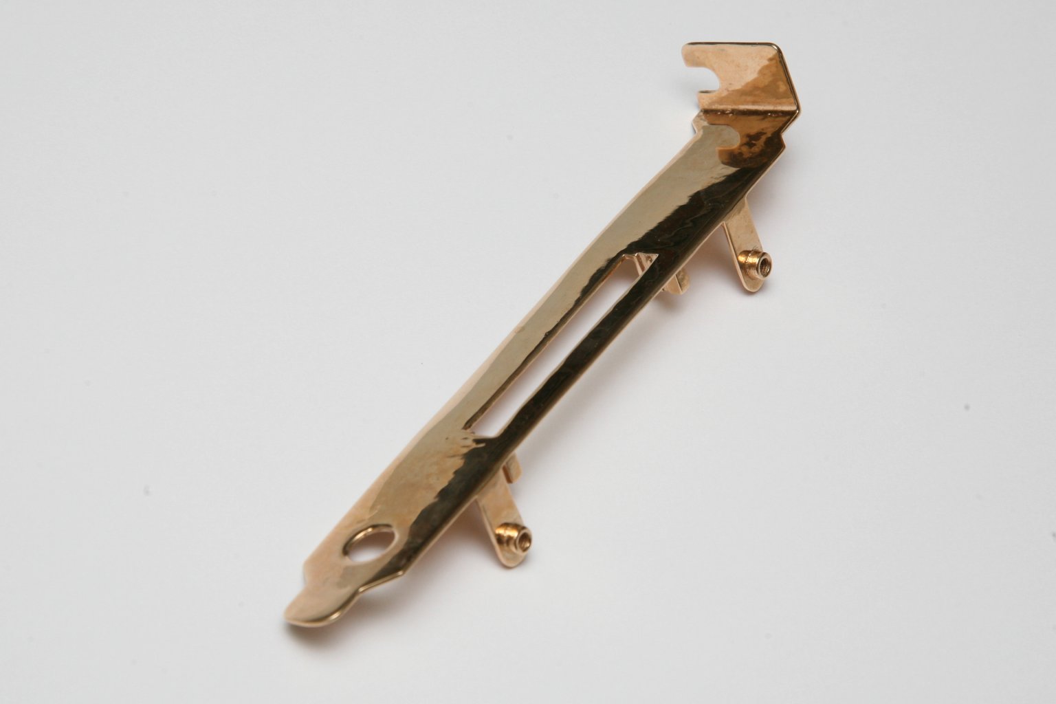
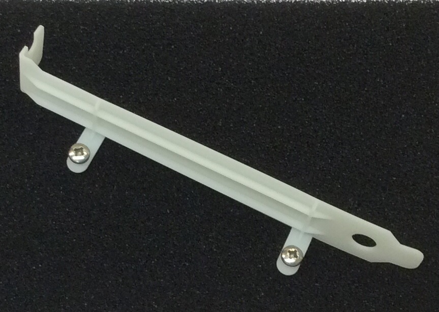
Weight is 19g, and though slightly ‘ripply’ along the flat surface, this bracket has a great, solid feel and seems sturdy enough to take the force required to insert the card. Currently this process is quite expensive, but of course that should come down given time.
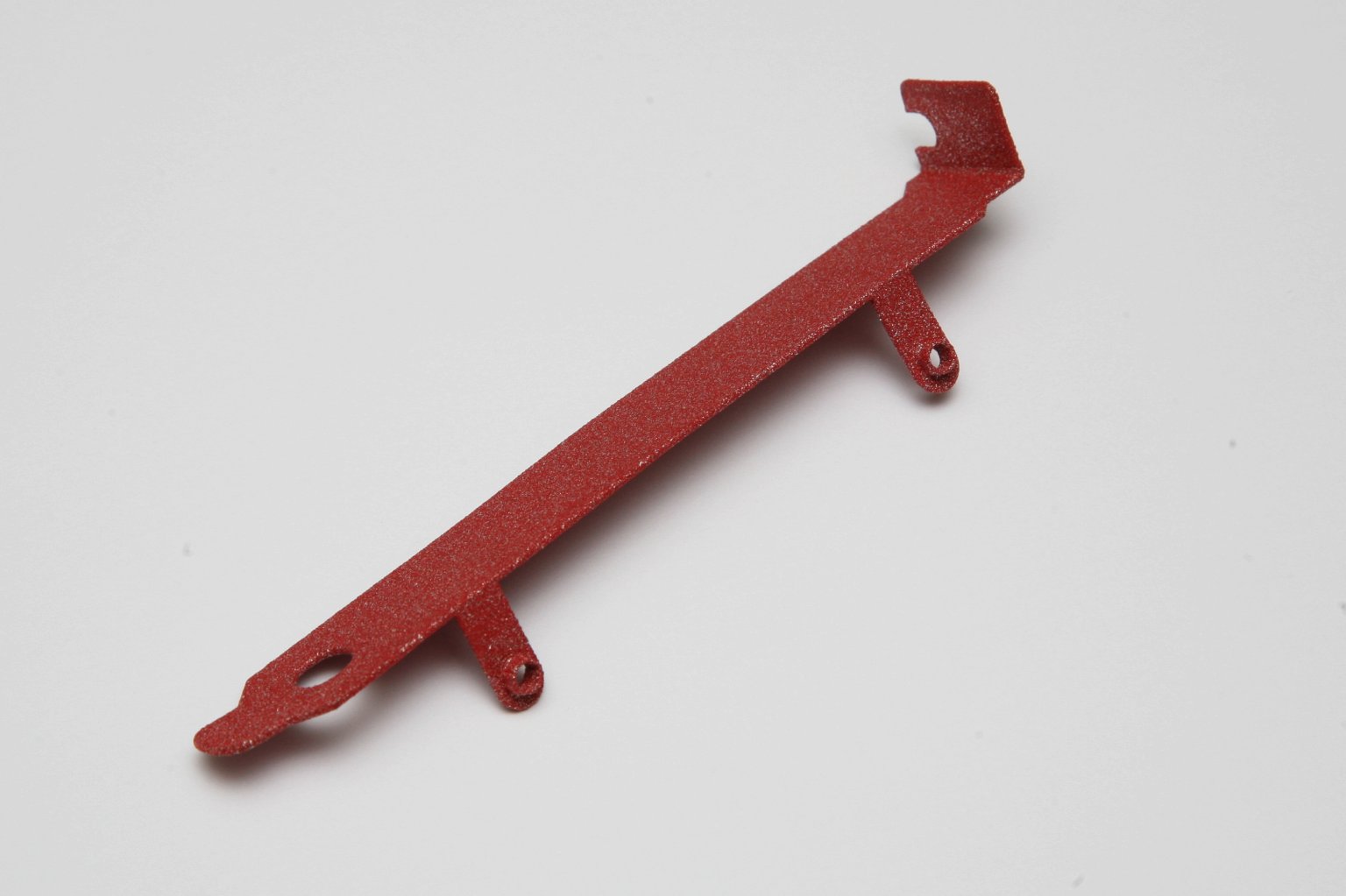
Unfortunately the PU coating on this prototype has left the card guides slightly too small for the CompactFlash card, but here’s a plain version (type 3), for example for the Lo-tech RAM, EMS, and 8-bit IDE adapters:
Another metal based material available is alumide, “a strong, somewhat rigid material that can take small impacts and resist some pressure while being bent. The surface has a sandy, granular look and is slightly porous”, according to the website.
This feels more like the SLA printed ABS, being quite bending and, at 3g, has a light-weight almost paper-like feel. Though certainly up to holding a card in situ, this bracket (like the ABS versions) isn’t strong enough to be used to apply force to insert or remove the card, so requires some care in use.
The bronze process is perfect for this application, just a little pricey at the moment. Stainless steel is another option (and actually gold and titanium too!) but is currently too expensive to seriously consider for this application.
The XT-CF-lite board arose almost out of frustration with the reliability issues in the CPLD based XF-CFv2, but it was instant hit – it’s probably the most-cloned Lo-tech board, with various unbranded re-spins appearing on eBay throughout Europe and Sergey’s through-hole version in the USA.
Following on from that, announcing then the rev.2:
What’s Changed?
Data bus buffer to ensure signal integrity in heavily loaded ISA buses
Simpler configuration (two options for ROM Address and IO address via simple jumpers)
As always, full details and schematic are available on the site wiki.
ISA Slot Bracket
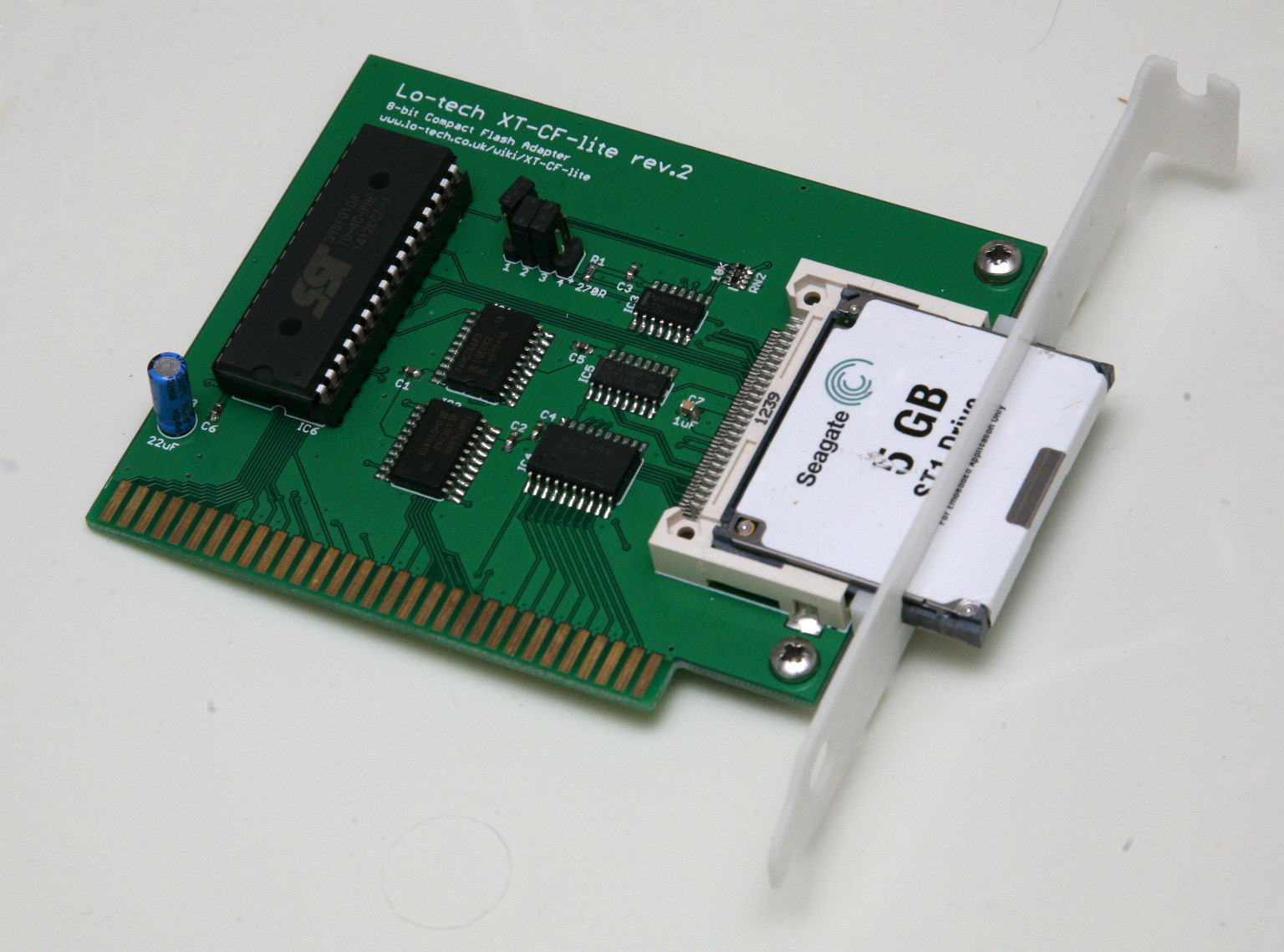
The pictured ISA slot bracket is 3D printed (SLA process) and includes guide rails and an exact Type II cutout, making it much easier to insert the card than with the previous punch-press bracket. The plastic is however fragile and though perfectly adequate once installed, it’s easy to break the tabs when fitting the card. 3D printing is however a rapidly evolving field and more prototypes, this time metal, are due towards the end of the month – watch this space!
Testing
Testing has been performed with this board in my ever-stable IBM Portable PC 5155. Besides the usual functional testing (flashing the BIOS and formatting media):
Copied 16,000 files (mixed of source and object code) totalling 1.2GB three times – on CompactFlash in slot 5 and again in slot 8, and on a Seagate ST1 Microdrive in slot 5. Files then binary-compared with no differences found.
Ran pattern tests totalling 128MB on CompactFlash and again on ST1 Microdrive, both in slot 5.
With over 1011 bits transferred, this card has already been tested to beyond the quoted soft error rate of the original ST-412.
Any CompactFlash card or Microdrive should work, however there are some more recent CompactFlash cards that appear to have dropped support for 8-bit transfer mode (despite this being a required feature in the specification). Cards I’ve tested include SanDisk’s Ultra II and Kingston 4GB, and Seagate ST1 Microdrives.
Performance
The performance of this card is identical to all other current Lo-tech XT-CF cards, it will do between 190 and 300KB/s in a PC/XT, depending on the mode and media capabilities – much faster than an MFM drive, which generally did more like 60 to 90KB/s. It can reach about 1MB/s in a 12MHz 286.
Availability
The XT-CF-lite rev.2 PCB is available now in the site store. This card will not be offered as a kit due to the difficulty in splitting and shipping SMT components – a full BoM is provided in the site wiki for easy ordering of components from Mouser.
ISA slot brackets can be printed either at home or through a 3D printing shop using the STL file available from the site wiki. Metal processes are now available – I’ll be posting a review of three options later this month!
2014 has been a great year thanks to your continued ideas and support, making possible prototyping and production of the super-niche products that Lo-tech specialises in. A huge thanks to everyone that’s been involved!
2015 will be even busier, and already I have a number of projects in-hand:
ISA CompactFlash PCB Rev.3 (with selectable ROM address)
8-bit IDE Adapter Rev.2 (with the errata fixed)
XT-CF-Lite rev.2 (with bus transceiver)
Raspberry Pi GPIO Board rev.2 (with more inputs, more outputs, and 1-wire bus)
New ISA slot brackets
New lines:
Roland MPU-401 adapter
Z80 Test Socket adapter
Other ideas including adding a forum to this site to enable users to more easily share their experiences getting things going and a new memory board combining ROM, RAM and EMS on one card.
But in the mean time – a very happy and prosperous new year!
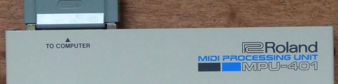
An email from a user of the Lo-tech XT-CF-lite caught my attention recently, the board being used in an IBM PC 5150 that’s being set up with the original Roland MPU-401 MIDI interface. It’s something I’d never looked at in detail, but a quick search quickly pulled up a couple of recent hardware projects to make compatible ISA interface cards for it. There’s an interesting article about the MPU-401 on the Nerdly Pleasures blog, but basically the system consisted of an ISA card (‘MIF-IPC’) in the PC connected to the MPU-401 via a 25-pin DSUB connector, which then provides MIDI outputs.
Multiple MPU-401s
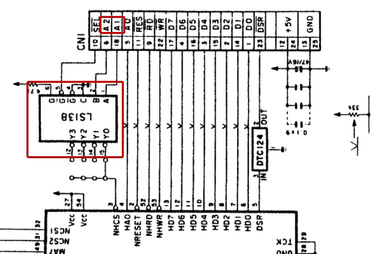
Flicking through the manuals then turned up something interesting… it looks like Roland had originally intended for up to four MPU-401 devices to be connected to the IBM PC, as the original MIF-IPC card sends A1 & A2 to the MPU-401, which then has fitted an ‘LS138 1-of-8 decoder:
By the time the second card was produced, the MIF-IPC-A, these lines had been simply connected to ground so effectively disabling this functionality. MIDI isn’t something I know anything about, but I’ve been told that having more than one MPU-401 attached would be “like going back to 1981 with an iPhone”!
Now of course software support would be another problem, and then there’s the question of whether the 8088 in the 5150 – or the ISA bus itself – is fast enough to keep them fed with data… but it’s something I’d like to at least have the option to try.
The Lo-tech MIF-IPC-B
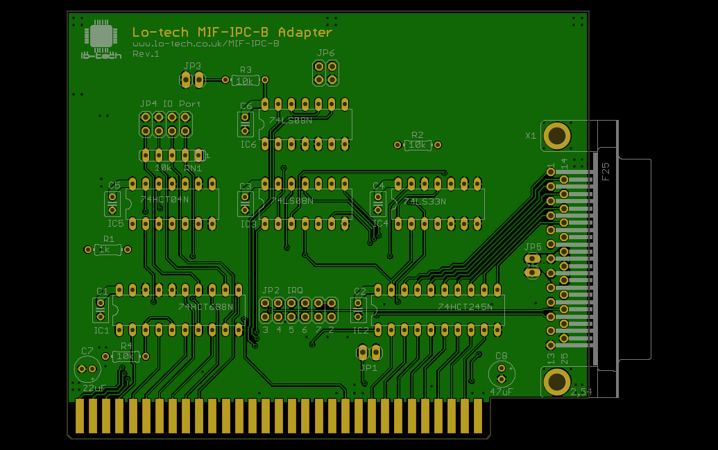
So, roll on another Lo-tech PCB…, I’m calling it the MIF-IPC-B, since it builds on the Roland MIF-IPC-A (by including the reset signal masking apparently need for compatibility with PC/AT systems) with some new features. Here’s the current GerbV image:
In terms of differences from the MIF-IPC-A, the board has:
Option to present A1 & A2 as either ground (like the MIF-IPC-A), or from the ISA Address Bus (like the original MIF-IPC), so making possible the connection of up to four MPU-401 devices to a single card
Option to work in PC/XT slot 8
Selectable IO port base address (15 options)
Selectable IRQ line (6 options)
Assuming this board works as intended, there will be some further work involved in getting multiple MPU-401’s hooked up, since the schematic clearly shows that the device ID is pre-selected on the PCB. I’m not sure many owners will be too keen on modifying the MPU-401 itself, but there are two ways of getting multiple devices hooked up with this card:
By using multiple cards, since the IO port can be individually selected, or
By running a short 25-pin DSUB lead to a break-out board, providing address decoding there and up to four DSUB connectors.
Using multiple cards isn’t a great option for 5150 owners, since the system needs a graphics board, a memory board, and at least one storage adapter (and likely two) meaning possibly only one slot free. For 5160 machines, the slot-8 compatibility of this board should make this a practical option, though this will still need testing.
Status
This board is currently at the design phase – any thoughts or ideas are welcome!
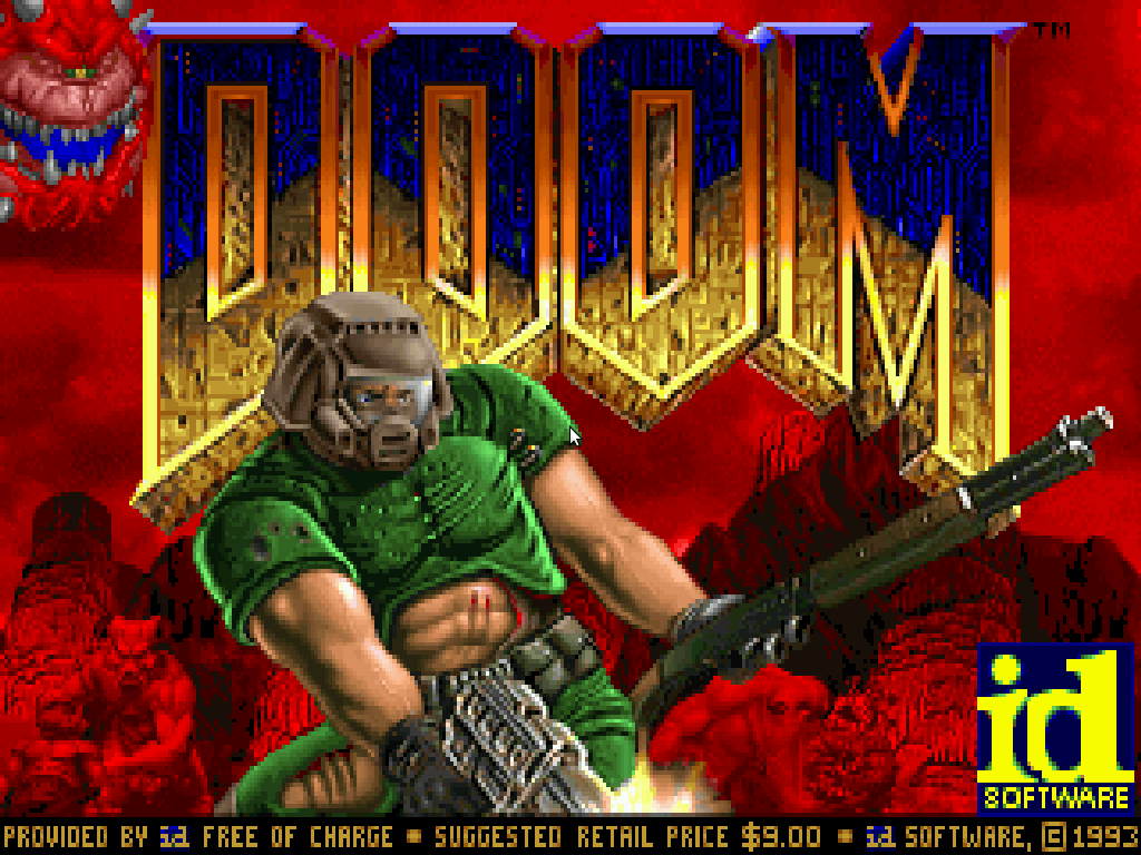
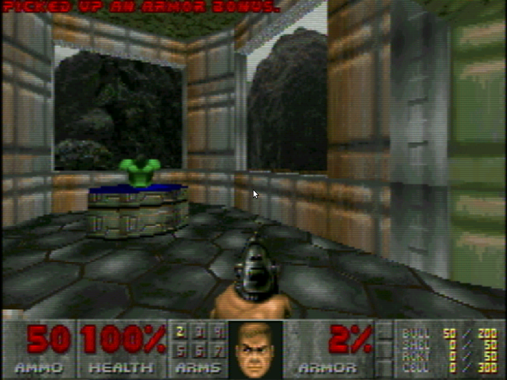
Being over 20 years since the release of Doom, I guess it now qualifies as lo-tech, and so the subject of some attention here. I’ve never been much of a gamer – but Outrun, Doom and Lemmings are three titles I still enjoy today.
Having stumbled across Chocolate Doom recently, the problem is that on a nice clear LCD screen 320×200 looks rubbish, certainly more blocky that I remember it looking on my Ambra 386 back in the day. Then again our expectations were I guess lower.
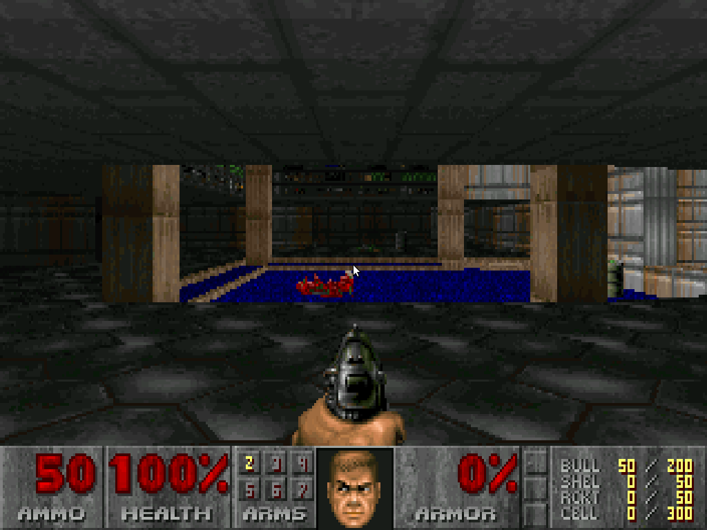
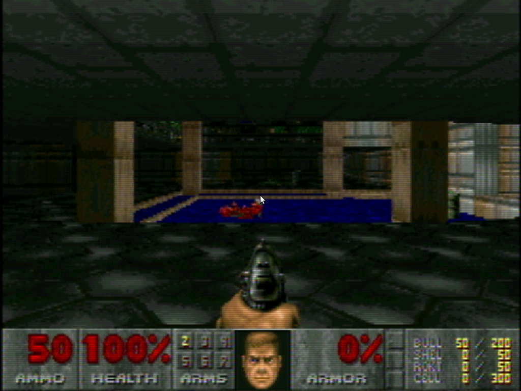
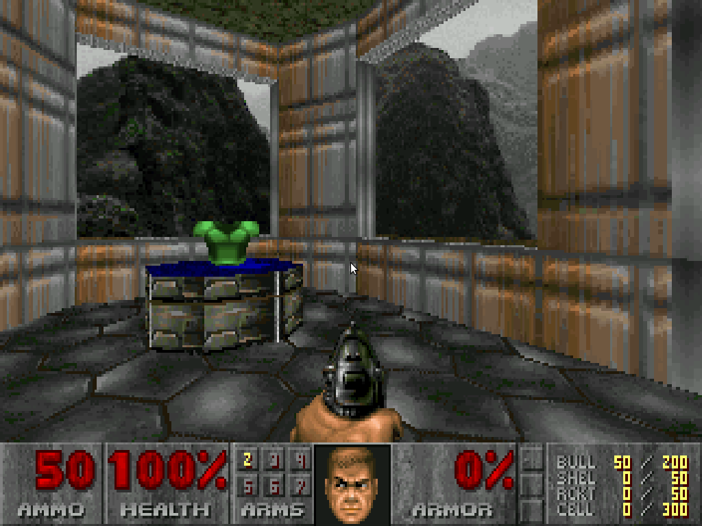
The results with Doom are, in my opinion, pretty good too (the difference is even more noticeable in-game, with moving images):
Native:Filtered:Native:
Filtered:Native:Filtered:Whilst I don’t claim to be a programmer, I’ve added the filtering code to chocolate doom and am making the entire code branch available for download right here. You’ll need to grab the Doom WAD file too (apt-get install doom-wad-shareware on Ubuntu).
To build the source (assuming it’s extracted to ~/chocolate-doom-filtered):
~$ cd ~/chocolate-doom-filtered
~/chocolate-doom-filtered$ ./autogen.sh
~/chocolate-doom-filtered$ make
~/chocolate-doom-filtered$ sudo make install
My coding is crude and so needs some specific settings in the config file (~/.chocolate-doom/chocolate-doom.cfg on Linux). Make this file by running chocolate-doom-setup, then edit it with a text editor to set:
I’ve changed the video initialisation code to start in full-screen, trying 1280×1024, 1024×768, 800×600 and finally 640×480 via standard SDL (1.x) calls. The game code renders via the configuration file settings (320×200) since that matches the original and minimised the CPU load of the filtering.
Once the game is running (chocolate-doom -iwad /usr/share/games/doom/doom1.wad on Ubuntu with the WAD files installed from doom-wad-shareware), a number of keys control the filtering:
f toggles the filter on-and-off
b reduces brightness, B to increase
c reduces contrast, C to increase
g reduces gamma, G to increase
h reduces hue, H to increase
i toggles interlacing effect
l reduces merging of frames (emulating CRT phosphor delay); L to increase
s reduces sharpness, S to increase
m cycles filter mode between composite, s-video, RGB and monochrome
It would be nice to use SDL 2 and hence offload the scaling to GPU via textures, however that’s beyond my skills. If you make any improvements to my code or port it to Android or IOS, please do post a comment and let me know!
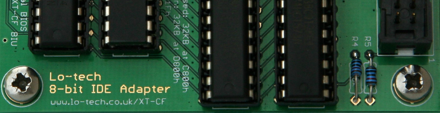
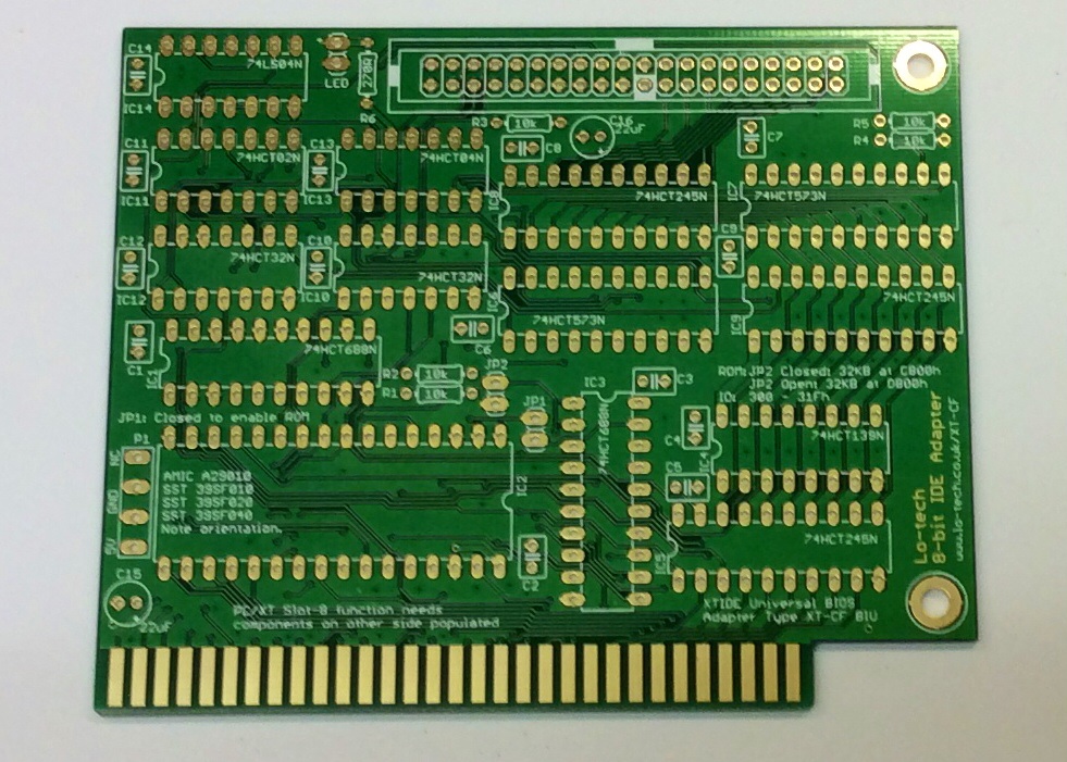
The Lo-tech 8-bit IDE Adapter is a bootable IDE controller for vintage PCs with only 8-bit ISA slots – basically PC/XT class hardware. The adapter is a development of the the Lo-tech ISA CompactFlash Adapter, adding an 8- to 16-bit MUX to make possible the use of normal hard drives, including current SATA drives (via an adapter like this). In this post, I’ll cover how to build the adapter and get it running.
Components
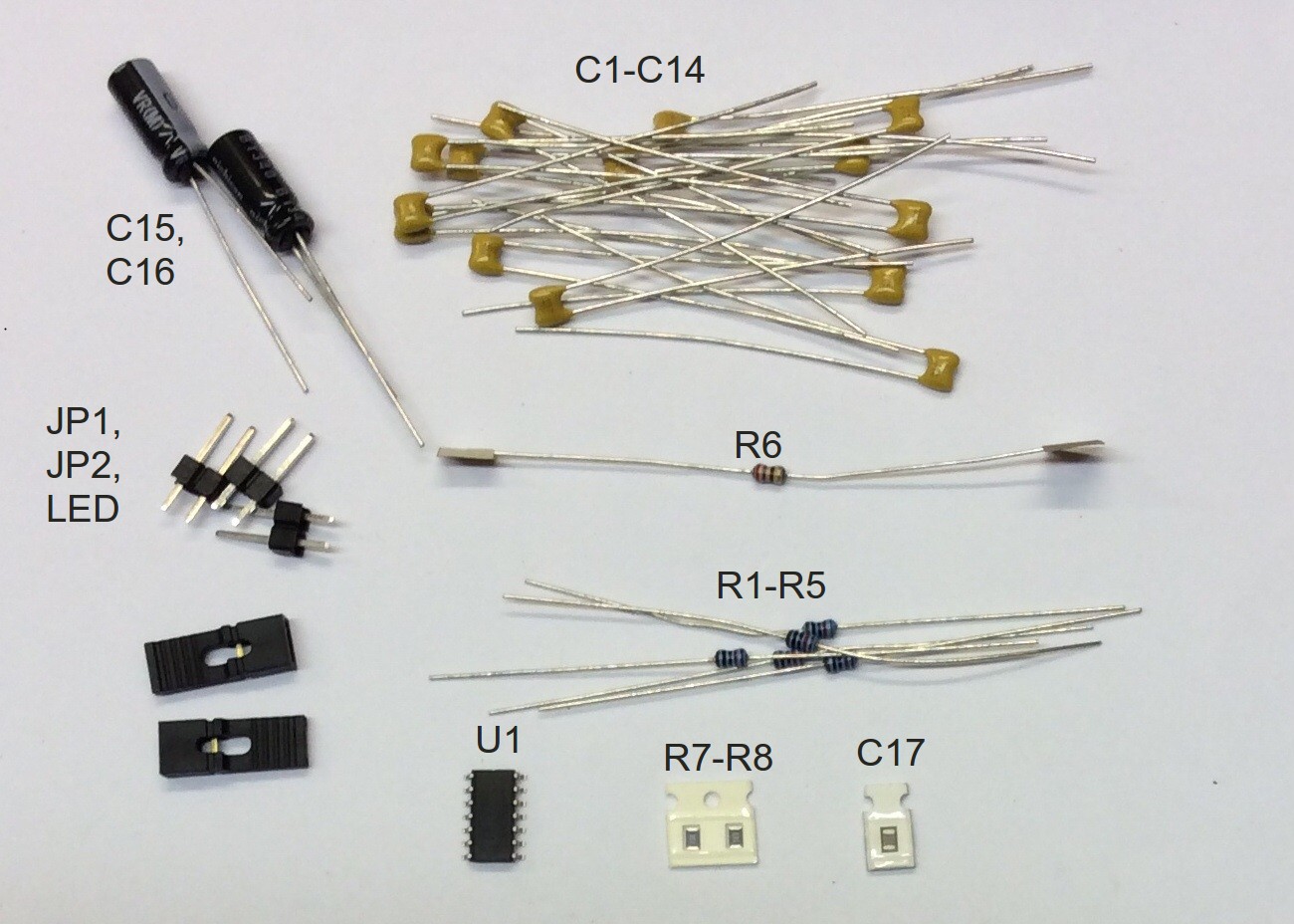
Here’s what’s in the kit bag:
The only tricky parts are the SMT parts on the solder side of the board, basically a SOIC 74LS33D and a few resistors. These parts provide IBM PC/XT Slot-8 compatibility and enhanced read performance in PC/AT class systems, and can be simply left of if that functionality is not required.
The Build
Build order is basically determined by the height of the components, so that they’re held in place whilst soldering:
SMT components first, if these are being used
Resistors R1 to R6
Capacitors C1 to C14
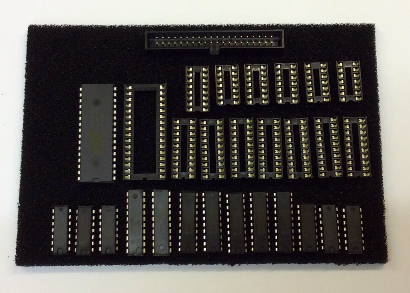
IC sockets. Check correct orientation (the notch should line up with the notch shown on the board silkscreen). Solder one pin of each first, then check the sockets are properly against the board. Once two or more pins are soldered, they will be very difficult to remove.
2-pin headers JP1, JP2, LED. As with the sockets, solder one pin first and then check alignment.
40-pin header HD1. First remove the key pin from the header using some small pliers unless key-pin provided 5V power is required (for example, to power a directly connected SATA converter). Again, solder one pin and then check alignment. Work quickly on each pin to avoid overheating the header plastic, otherwise the pins can become misaligned.
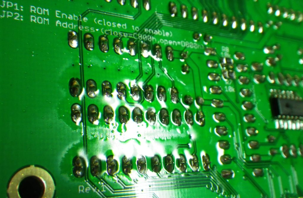
At this point the board will have a lot of flux residue that needs to be thoroughly cleaned off:
The board can be cleaned by immersion in either warm de-ionised water, isopropynol, or a specific flux remover and gentle agitation with either a toothbrush or an ultrasonic cleaner. Once satisfactorily cleaned, the two electrolytic capacitors C15 and C16 should be added, and the respective soldering areas cleaned again.
Once cleaned, check the joints thoroughly for any dry-joints or bridges (shorts), particularly around the SMT components (if fitted).
Finishing the Board
With the soldering done all that’s left to do is to dry thoroughly, for example with warm air (i.e. a hair dryer), add the ICs and slot bracket, then flash the BIOS.
Before the ICs can be fitted to the sockets, the pins need to be aligned using an alignment tool like this (ICs provided in Lo-tech kits are shipped ready aligned).
Errata
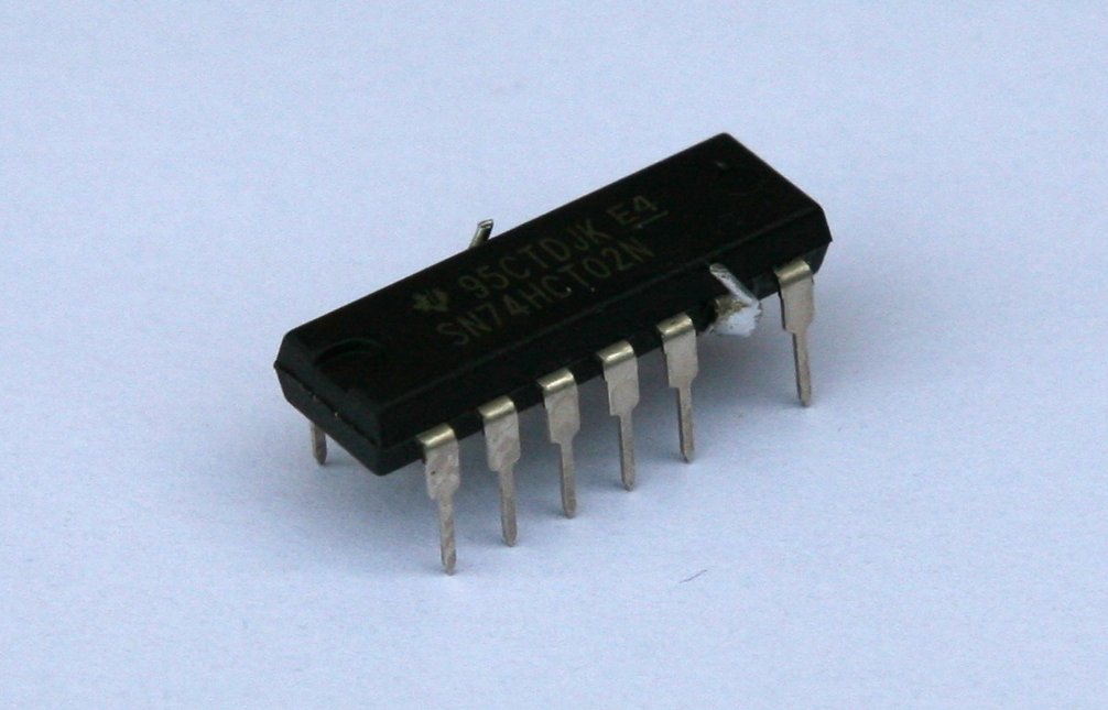
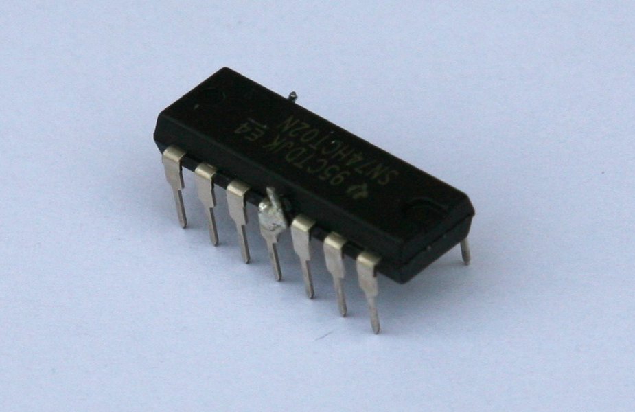
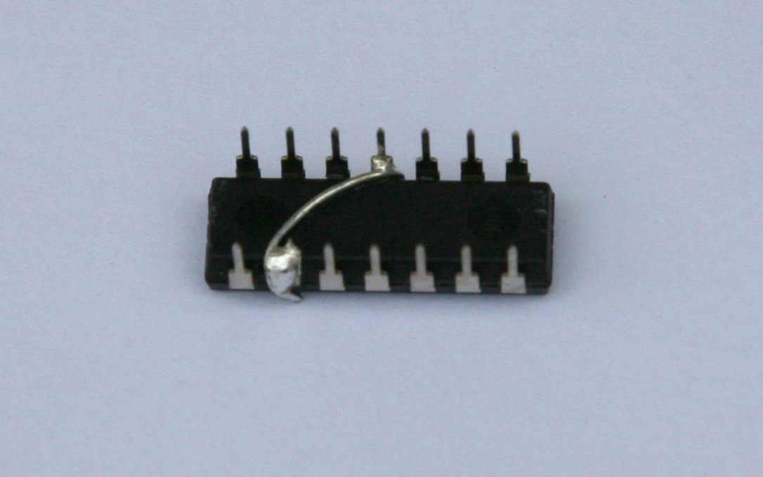
The first version of this board contains one error, which can be fixed by modifying the 74HCT02N that will be fitted as IC11 – pin 6 should be jumpered to pin 11, and pin 6 clipped or bent so it doesn’t make contact with the DIP socket. Here’s what the mod looks like (click on the images for a larger view) with the off-cut from a resistor used to make the connection:
Without this modification, the write latch load signal is masked unless the request is port 0, which works for the data register but also means no commands can be issued to the drive! Instead, the signal should be masked only when the request is port 1, which as it happens is on pin 11 already. Note that this modification applies only to the first revision boards; no modifications are required for the Rev.2 board.
Mounting the Chips
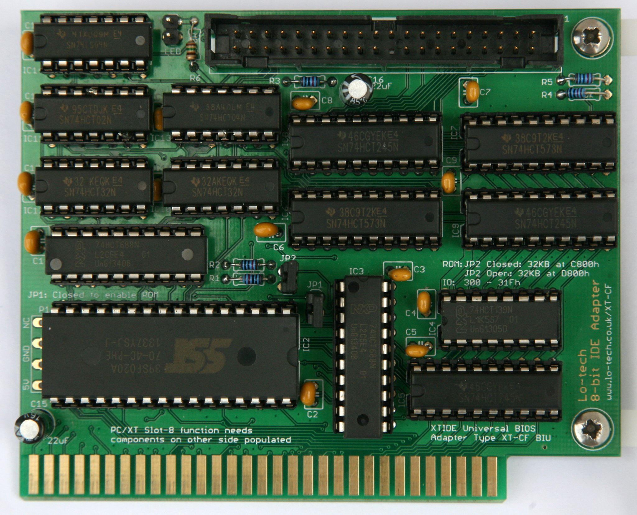
Once the pins are aligned, the chips can be mounted in the sockets, Ensure the chips are fitted in the correct orientation, shown by the notches. Here’s a finished board, for reference:
Flashing the BIOS and Testing
Once assembled and fitted in a PC, the BIOS needs to be stored in the flash chip on the card. There’s no external EPROM programmer needed – the chip can be flashed directly from DOS in the machine, using the Lo-tech FLASH utility.
Depending on how JP2 is set, the command needed is either (assuming the ROM image from the wiki is being used):
A:\>flash 8bit-ide.bin c800
or
A:\>flash 8bit-ide.bin d800
Once this has been done, reboot the PC and the XTIDE Universal BIOS should be displayed after the system POST, and any connected hard disks detected.
To get the machine to boot from the adapter, the primary disk will need to be partitioned (a primary and active partition created, using DOS FDISK utility) and then formatted (FORMAT C: /S). If the disk has been used with a newer operating system (anything other than DOS), a new Master Boot Record is probably needed as well, which can be created using DOS 6.22 by running FDISK /MBR.
PCB and Kit Availability
Rev.1 PCBs and kits are available in the store now – note these need one of the 74HCT02 chips modified as detailed above as part of the assembly process.
Lo-tech is in no way associated with the sellers of products on other sites linked to on this page (which are provided to provide an example of the types of products available).
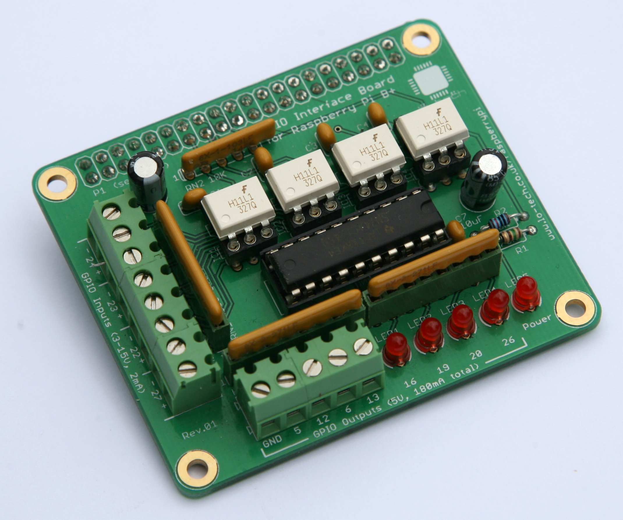
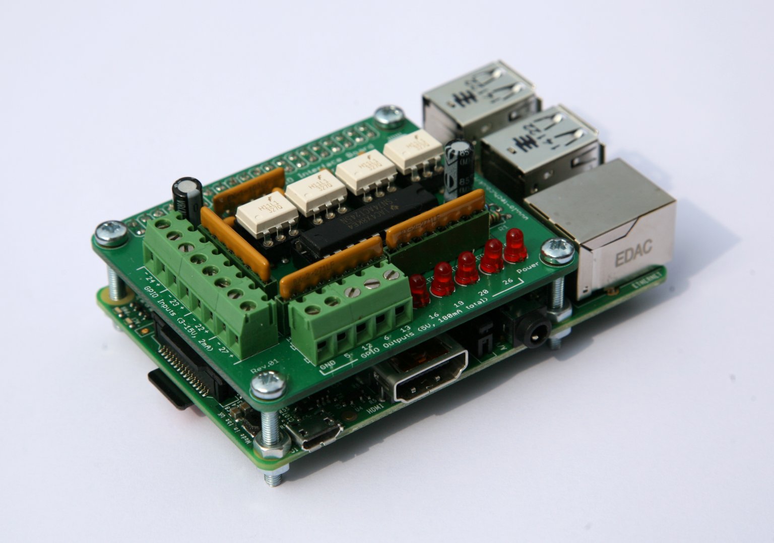
This is the first Lo-tech PCB not targeted at retro computing directly, but the Raspberry Pi is of course an interesting hobby ecosystem in its own right and something that can find a practically unlimited range of use-cases. Looking around for a GPIO interface for the new model, I couldn’t find anything available (OK that was immediately at launch of the new model) and certainly nothing that offers a Radio Shack style build-it-yourself experience, hence why this board now exists.
This board connects directly to the expansion header on the new Mobel B+ Raspberry Pi, and provides 4 opto-isolated inputs and 8 outputs. When powering 8 LEDs and being polled a few times a second, the power consumption of the Raspberry Pi with the board fitted is only around 1-2 Watts, making this combination particularly suitable for embedded applications such as network connecting things around the house for monitoring or alerting.
The board follows the design of the Raspberry Pi B+, making for a tidy installation:
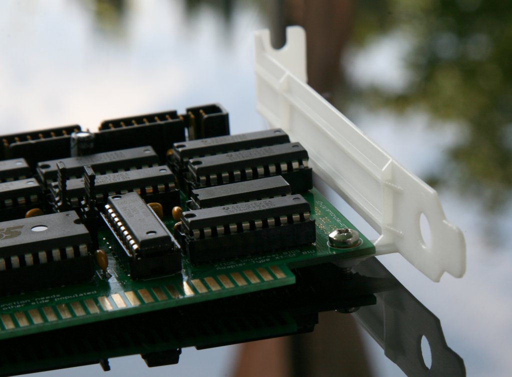
My first attempt at an ISA slot bracket produced on a 3D printer (see here) went reasonably well, with the result perfectly able to do the job of supporting the cards in the slot. But they were a bit more bendy that I’d hoped, so here is a revision 2 with ribs running down the length and either side of the card mounting fingers:
These have again been printed with a high definition SLA process and are much less flexible than the first version. These look good installed and do the job of holding the cards upright perfectly:
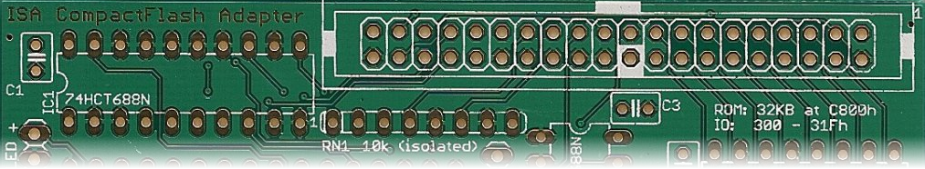
The Lo-tech ISA CompactFlash kit makes it possible to boot a vintage PC from a CompactFlash card in a straight-forward through-hole soldering project by means of a cheap CompactFlash-to-IDE adapter (like this). Whilst there’s long been interest in a similar SD-Card storage option, CompactFlash has always been just so much easier since it was designed for the ISA bus and supports an 8-bit transfer mode natively.
The development process for the (forthcoming) Lo-tech 8-bit IDE Adapter meanwhile involves testing as many different drives as possible, and it was perplexing that an SD-Card-to-IDE adapter just wasn’t detected, given that all the real hard-drives so far tested worked OK. This got me thinking.
Test BIOS
In hacking the XT-IDE Universal BIOS (XUB) to work with the new 8-bit IDE adapter, I’ve simply re-used the existing XT-CF ‘BIU’ controller type (designed for CompactFlash and so making use of the 8-bit transfer mode) and bypassed the error checking on the 8-bit mode set command. This allows the disk to stay in 16-bit transfer mode (because generally 8-bit transfer mode isn’t supported by real hard-disks) and leaves the magic to the hardware on the 8-bit IDE Adapter. This works OK, but… what if the SD-to-IDE adapter actually supported 8-bit transfer mode?
In that case, the BIOS would set 8-bit transfers, then only ever retrieve half the sector data interspersed with random garbage, since the logic on the new adapter would be storing the high 8-bits which we’d just configured the device not to present. So could the SD-to-IDE adapter work on the ISA CompactFlash adapter?
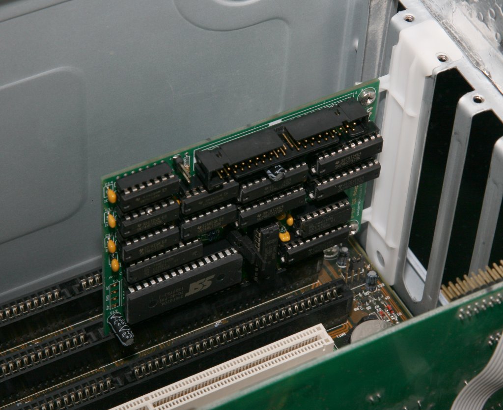
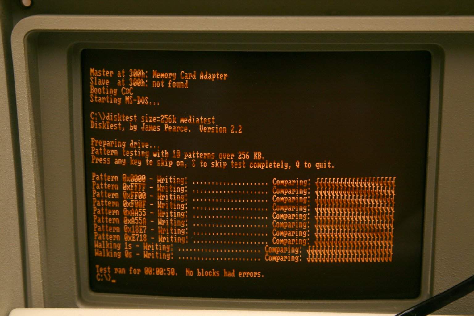
Lo-tech ISA CompactFlash Adapter booting from an SD card interfaced via an FC1306T based adapter
FC1306T (GP)
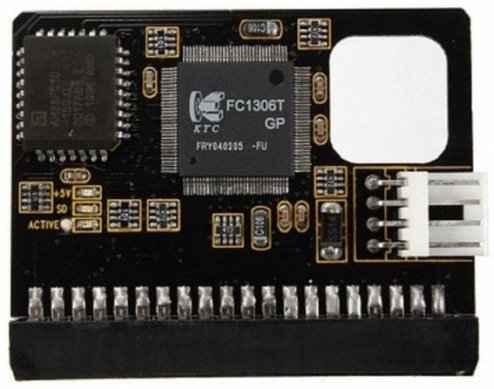
The SD-Card adapter I was testing was based on the FC1306T chip, and the answer is right there in the datasheet: it’s actually an SD-to-CompactFlash adapter, “Fully compatible with CFA (Compact Flash Association) Standard”, which of course includes 8-bit transfer mode.
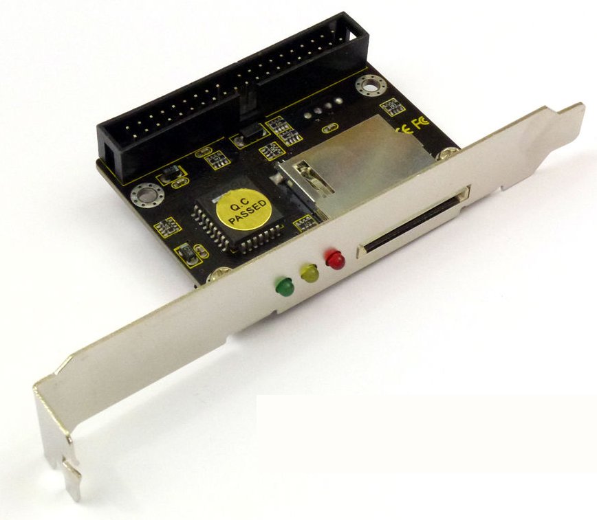
FC1306T based adapters seem to be in plentiful supply – in header, cable or slot-mount types, and any adapter based on this chip should work!
FC1306T based SD-Card to IDE adapters support 8-bit transfer mode
Performance wise these run at about the same speed as a basic CompactFlash card – around 200KB/s in an otherwise stock PC/XT. The slot-mount type need some care in mounting as they have PCI profile brackets, with the card mounted on the other side. I found it could be bent a little for use in an IBM Portable PC 5155 slot 8, providing externally accessible SD card storage and using a slot of otherwise limited use.
SD card throughput in an otherwise stock IBM Portable PC 5155
Lo-tech is in no way associated with the sellers of products on other sites linked to on this page (which are provided to provide an example of the types of products available).
This website uses cookies to improve your experience. We'll assume you're ok with this, but you can opt-out if you wish.AcceptRead More
Privacy & Cookies Policy
Privacy Overview
This website uses cookies to improve your experience while you navigate through the website. Out of these, the cookies that are categorized as necessary are stored on your browser as they are essential for the working of basic functionalities of the website. We also use third-party cookies that help us analyze and understand how you use this website. These cookies will be stored in your browser only with your consent. You also have the option to opt-out of these cookies. But opting out of some of these cookies may affect your browsing experience.
Necessary cookies are absolutely essential for the website to function properly. This category only includes cookies that ensures basic functionalities and security features of the website. These cookies do not store any personal information.
Any cookies that may not be particularly necessary for the website to function and is used specifically to collect user personal data via analytics, ads, other embedded contents are termed as non-necessary cookies. It is mandatory to procure user consent prior to running these cookies on your website.
Lo-tech products are sold via TexElec. Please visit their web site texelec.com. Dismiss