Archives for james

Lo-tech 8-bit IDE Adapter MUX Design

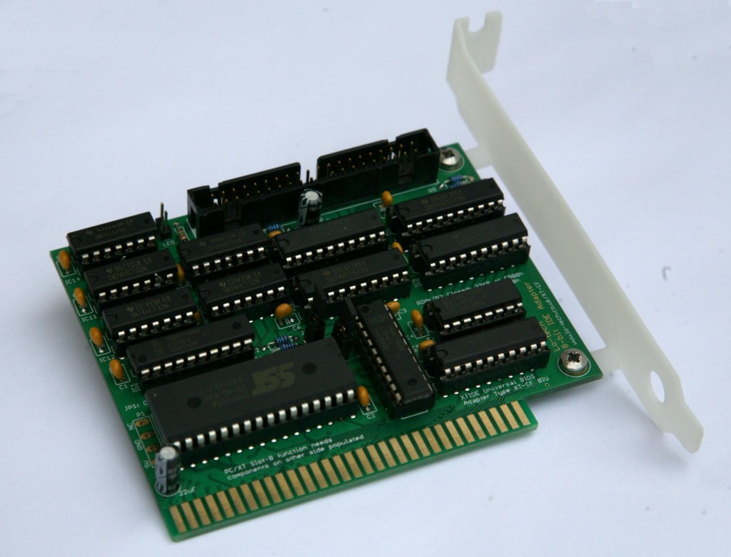
8-bit-ide-rev1-banner-2The Lo-tech 8-bit IDE Adapter is a bootable IDE controller for vintage PCs with only 8-bit ISA slots – basically PC/XT class hardware. The adapter is a development of the the Lo-tech ISA CompactFlash Adapter, adding an 8- to 16-bit MUX to make possible the use of normal hard drives, including current SATA drives (via an adapter like this). In this post, I’ll cover how the adapter works.

16- to 8-bit MUX Design

The main design goal with this adapter is to enable the use of standard, 16-bit drives (‘ATA drives’) with PC/XT class hardware. ATA drives all use both 8- and 16-bit data transfers:

  • Port 0 – 16-bit data port. This is where the actual sector data is transferred
  • Port 1 to 7 – 8-bit command ports. This is how the drive is told what to do next, like read or write to a sector.

Port IO with 8-bit ISA Cards

In the IBM PC, port IO can also be either 8- or 16-bit, even in XT class hardware with 8-bit ISA slots. Logic in the system known as the bus interface unit (BIU) makes this possible by breaking 16-bit instructions into two consecutive 8-bit bus cycles at consecutive 8-bit port addresses. Hence a single 16-bit port IO is, with 8-bit ISA cards, exactly equivalent to two consecutive 8-bit port IOs:

8-and-16-bit-port-IO

8-bit ISA cards can still use 16-bit CPU instructions (MSB=most significant byte, LSB=least significant byte)

Note that this applies specifically to hardware in 8-bit ISA slots; when a 16-bit instruction is used with a 16-bit device, all 16-bits are transferred in one bus cycle (and via a single, port 0 in this example). This difference provides both a problem and an opportunity – the ATA specification defines port 0 (only) for (the 16-bit) data transfer, so it just won’t work ‘as-is’ via an 8-bit slot, but secondly the CPU and BIU will already deal with one half of the equation. The 8-bit adapter just needs to break apart 16-bit drive IO into two ISA bus cycles, without the drive noticing.

Port Remapping

Making ports 0 and 1 free for the ATA data register is straightforward – just shift all the command addresses left one bit, a trick already used in the XT-CF line of adapters. With the BIOS code similarly updated, it makes no difference to the drive and this then means address line A0, which distinguishes port 0 from port 1, is free for the adapter to use for something else.

With that in place, 8- or 16-bit port IO can be performed to any of the drives registers, though the ATA specification only calls for 16-bit IO on the data register.

The MUX

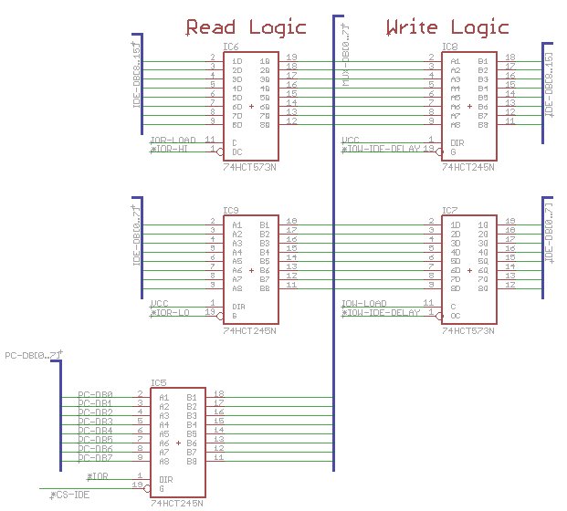
The 8- to 16-bit MUX itself uses a separate 74HCT573 and 74HCT245 pair for reads and writes, and another 74HCT245 to link back to the PC data bus. The ‘573 is a latch (like a one-byte memory) providing temporary storage, and the ‘245’s are buffers that can be switched on at will, enabling isolation of certain signals when required.

8-bit-ide-rev1-mux

For reads:

  • First bus cycle: a 16-bit word is transferred from the drive. The LSB is presented to the PC data bus and the MSB stored in a latch.
  • Second bus cycle: data from the latch is presented to the PC data bus, and the IO signal to the drive suppressed.

For writes:

  • First bus cycle: LSB presented on the PC data bus is stored in the latch, and the IO signal to the drive suppressed.
  • Second bus cycle: MSB presented on the PC data bus is presented to the drive interface MSB, and data from the latch is presented to the drive LSB.

Interface Timing

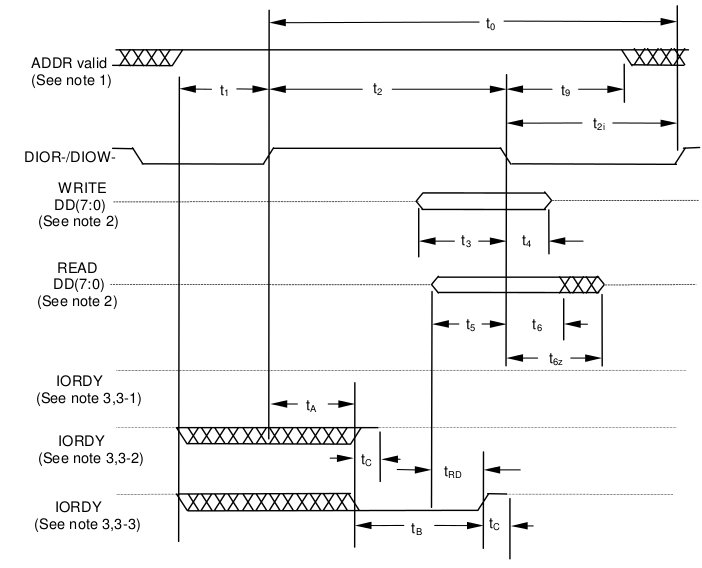
The timing of this process needs some consideration as we need to be sure that data is stored in the appropriate latch before it disappears from the data bus, and secondly that data is presented until just after whatever is receiving it has stored it – this is measured as the data hold time.

ata-interface-timing-diagram

ATA Interface Timing Diagram

For ATA mode 0, the specified data hold times are 5ns for reads (t6), and 30ns for writes (t4).

  • For writes, to keep data presented after DIOW line is released at the drive, the latch and buffer outputs are fed from the delayed signal (*IOW-IDE-DELAY in the schematic)
  • For reads, the hold time specification of the ‘HCT573 must be observed (9ns). The data being presented by the drive is held beyond the latch time since the drive DIOR line is fed from the delayed signal.

The delays are made by feeding the respective signals through three NOT gates (the control logic already inverts it once) in IC14. The delay can be controlled by the component choice (~15ns with SN74LS04N, or about 25ns with SN74HCT04N). Without the delay lines, for example in the case of a write the latch output would be turned off just as the drive latches the data because of zero hold time – the data may or may not still be valid as the drive stores the data.

PCB Errata

In the first version of this board, the write latch load signal is masked unless the request is port 0, which works for the data register but also means no commands can be issued to the drive! Instead, the signal should be masked only when the request is port 1, which can be fixed by modifying the 74HCT02N that will be fitted as IC11 – more details to follow in a build post.


Lo-tech is in no way associated with the sellers of products on other sites linked to on this page (which are provided to provide an example of the types of products available).

New PCB: 8-bit IDE Adapter

8-bit-ide-rev1-banner-2


The lo-tech ISA CompactFlash adapter continues to be the top selling lo-tech project kit, providing a bootable fixed disk option for vintage PCs with the added satisfaction of being something that can made by the hobbyest. But one question just keeps coming… can it be used with a real hard disk?

The answer is yes, but only ATA-2 disks (typically 80 to 250MB and obviously now long past their use-by date) as it depends on ATA-2 8-bit transfer mode, which of course is still supported by all CompactFlash cards. This makes it relatively simple and small enough for the Sinclair PC200 that was the design motivation. The 40-pin IDE header just avoids fiddly surface-mount CompactFlash headers – adapters are available on eBay very cheaply (random product link).

So to answer the continuing demand for an adapter compatible with all normal IDE drives, I’ve taken the ISA CompactFlash adapter design and added the 16- to 8-bit logic (the MUX) to make it work with normal drives – including SATA drives and SD cards via appropriate adapters (random links: sata adapter, SD adapter). This has doubled the PCB size and increased the chip count from 6 to 15, but here it is!

The Lo-tech 8-bit IDE Adapter is an IDE controller for 8-bit ISA slots that works with normal IDE and SATA drives

Adapter In Action

The detail of how the adapter works I’ll cover in another post, but for now here is an IBM PC 5155 booting up from it and running some pattern tests:

8-bit-ide-rev1-boot-and-pattern-test

Testing so far is limited, but all drives tested have worked, including two SATA drives. Performance wise, it runs at about 250KB/s with a 4.77MHz 8088, and I’d expect about 400KB/s with a V20 (thanks to the REP INSW optimisation).

More details, and PCBs, coming soon!

Lo-tech is in no way associated with the sellers of products on other sites linked to on this page (which are provided to provide an example of the types of products available).
3D Printed ISA Slot Brackets

I’ve wondered for a while whether the custom designed ISA slot brackets used by lo-tech PCBs would be any good made with 3D printing. The technology is obviously progressing rapidly, with the price of home machines tumbling and commercial services now offering a variety materials and processes (including some metals).

The first step was to create a 3D model of the brackets from the simple sketches, for which I opted for OpenSCAD. It’s a kind-of programming language that allows the design to be described precisely in code, for example a bit of code looks like this:

union() {
 linear_extrude(height=z) {
 roundedRect([x,y],0,0,3,3);
 }
 translate([(x/2),holepos,-2]) linear_extrude(height=(z+2))
 circle((thread/2)+0.5,$fn=20);
}

Once the shape has been defined, the software then renders it on-screen and produces a bunch of stats about the object generated. Here’s the rendered shape of the lo-tech type 3 bracket:

Lo-tech-ISA-Slot-Bracket-Type-3-Design

This can then be exported to a suitable format for manufacturing, like STL. Two things I learnt:

  • The 3D shapes are unit-less, that is to say that the fabricator needs to know what a measurement of 1 means. Most online quoting tools allow the selection of inches or mm.
  • When rendered, OpenSCAD produces some stats. To be made successfully, a shape must be simple and have 2 volumes.

With that sorted and an order for both FDM and SLA processed brackets placed, a few weeks later the first prototypes dropped through the door. The FDM process had a great textured finish and was quite stiff, but was too brittle at least at the specified 1mm thickness, and the M3 screw threads couldn’t be printed. The SLA process produces a way more flexible and high-resolution product accurate enough to have working M3 threads. This is therefore the chosen process for the brackets now available for the lo-tech EMS, RAM and soon-to-be-released 8-bit IDE PCBs:

Lo-tech-ISA-Slot-Bracket-Type-3

3D Printed brackets for lo-tech EMS and RAM boards are available in the store now.

ISA ROM Board Updated

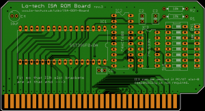
The Lo-tech ISA ROM Board is a simple and cheap to make 8-bit ISA board that provides a 32 or 64KB ROM via a flash chip, and was first released in 2012 primarily to help with XT-IDE Universal BIOS development. It now enters it’s third revision, adding PC/XT Slot-8 support.

isa-rom-board-r3-front

The board retains all the previous features, including selectable 32KB or 64KB operating modes, in-system programming, extensive address selection options, and entirely through-hole component choice for easy home assembly.

This kit is ideal for anyone tinkering with IBM PC BIOS or option ROM development, or as a handy flash ROM to add option ROMs for example to support high density floppy, IDE controllers without their own ROM, or network boot (like ATAoE).

Availability

CADSoft Eagle PCB design files and associated Gerbers (which are used by PCB fabricators) are all available now (with the usual Lo-tech GPL derived license) via the site wiki.

PCBs and full kits will be available via the Lo-tech shop at the start of May.

1MB RAM and 2MB EMS Boards Updated

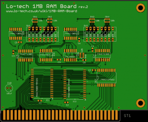
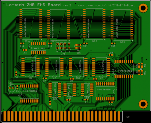
Introduced back in February, the Lo-tech 1MB RAM Board and 2MB EMS Boards have been undergoing basic testing since, and have now both been updated to rev.2 designs, with a number of fixes and changes to make them ready for release. The designs files for both boards are available now via the site wiki.

1MB-RAM-Board-r02-Top 2MB-EMS-Board-r02-front

Along with a few component changes and the addition of configuration information on the silkscreen, the main changes are the addition of PC/XT slot-8 compatibility to the RAM Board, and a better choice of IO port addresses on the EMS Board.

Both boards now also use the same mounting hole placement, meaning a new ISA slot bracket, which is currently in development.

Availability

CADSoft Eagle PCB design files and associated Gerbers (which are used by PCB fabricators) are all available now (with the usual Lo-tech GPL derived license) via the site wiki. The EMS driver source will be added soon.

PCBs and full kits will be available via the Lo-tech shop at the start of May.

New Lo-tech PCBs: RAM & EMS

RAM chips in early 1980’s PCs are a fairly regular cause of problems, and then there’s the issue of only have some meager amount of RAM installed on the system board, as little as 16KB on the first IBM 5150.

Mostly RAM is expanded up to the maximum (usually 640KB) via a multi-function ISA expansion card, but these boards don’t provide upper memory blocks (above 640KB) nor generally EMS, a memory expansion technology for 8088/8086 PCs providing up to 32MB defined by Lotus, Intel and Microsoft. For that, something like an Intel AboveBoard is required, which is a full-length and now rare card.

So, enter two new lo-tech PCBs, both built on AS6C4008 4Mb SRAM chips:

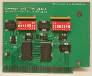
1MB-RAM-Board-Assembled

1MB RAM Board

The lo-tech 1MB RAM board, providing from 48KB to 1MB of system RAM, with each 64KB page individually switchable to provide a universal expansion board for any 8-bit PC, regardless of how much RAM is installed on the system board. The first 16KB can also be switched off, enabling its use with a stock 16KB 5150.

2MB EMS Board

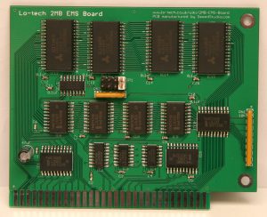
2MB EMS Board

The lo-tech 2MB EMS board, providing from 512KB to 2MB of LIM 3.2 expanded (EMS) memory (available capacity is dependent on how many SRAM chips are populated). Applications like Lotus 1-2-3 and Windows 2.x and 3.0 will use EMS when available.

Both boards are built on 1.27mm pitch SMT components in order to fit everything on the available 80x100mm Eagle Lite routing area. Assembly of these components is perfectly acheivable at home – see the lo-tech SMT soldering guide.

These boards are both in first-prototype testing phase and so should not yet be considered fully functional; some refinements are likely in future revisions. Initial test results have though been positive – using the lo-tech test-bench IBM 5155:

  • The RAM board is detected as configured on the DIP switches and the machine is able to run through Trixter’s 8088 Corruption (which utilises all available RAM) without issue
  • The EMS board is correctly identified by a low-level test routine and passes basic page register and fill operation tests

But, more test hours are needed and the driver for the EMS board is yet to be written – that’s work-in-progress!

ISA CompactFlash Parts Kit Available Now!

The Lo-tech PCBs are proving popular, especially the ISA CompactFlash PCB, the XT-CF-lite PCB and the TRS-80 IDE Adapter PCB.

The most common requests are for fully assembled boards or complete parts kits, so I’m now pleased to announce the availability of full kits for the ISA CompactFlash board, available now!

The kit contains everything needed to build a fully functioning board to allow the connection of a CompactFlash card, via a cheap Compactflash-to-IDE converter like this one or this one (randomly picked; I have no connection with the sellers) to an 8088 or 8086 based IBM compatible PC.

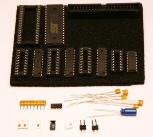
In the parts bag are the ICs and sockets pressed into some antistatic foam, and a number of loose components – everything on the Bill Of Materials:

ISA CompactFlash Parts Kit Contents

ISA CompactFlash Parts Kit Contents

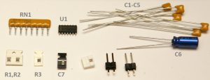
The loose components are:

isa-compactflash-parts-identification

Once assembled, the XTIDE Universal BIOS must be programmed onto the card. This can be performed with the card installed in the PC (no external EPROM programmer is required) using the lo-tech Flash utlity and the pre-configured ROM image. This requires having some way to transfer the utility and image file to the target system, for example by floppy disk. If you don’t have this capability, the ROM can be programmed in an external programmer, or the kit can be shipped with the ROM ready-programmed – just add the Flash Chip Programming Service for each kit purchased.

TRS-80 IDE Hard Drive Interface

tandy-banner

A thread on vintage-computer.com forum recently caught my eye, member Firebox have breadboarded a simple and low-cost IDE adapter based on a design by Larry Campanell for the TRS-80 Model 4 range, enabling connection of standard IDE drives.  It seemed like an ideal project to turn into a lo-tech PCB.

It turns out there’s already a bootable IDE solution, the FreHD project, providing access to disk images stored on a FAT32 formatted SD card powered by a PIC microcontroller. It does look fantastic, but I felt there could be space for something simpler (and so cheaper) as well.

The prototyped low-cost adapter needs just a few 7400 series ICs, and simply ignores half the data coming from the IDE device to provide the 256-byte sectors the TRS-80 expects. The designer though notes some compatibility issues:

I did have one problem, though — not all IDE drives would work….only one of the four IDE drives I tried would work.

That sounded familiar – I’d been through the same developing the CPLD logic for the XT-CF series.

Timing

When the CPU accesses a device, it first provides the address (IO Port) then the read or write signal.  In the Z80 world the CPU generates the same address, read (RD) and write (WR) signals for memory or IO port addressing, the two being distinguished with IO-Request (IORQ) or Memory Request (MREQ) signals.

In the TRS-80 expansion interface (model 3/4/4P), the system combines IORQ, RD and WR signals to provide simple IN and OUT signals along with the address bus, also providing IORQ and M1 signals for reference which can be used to identify interrupt acknowledgement.

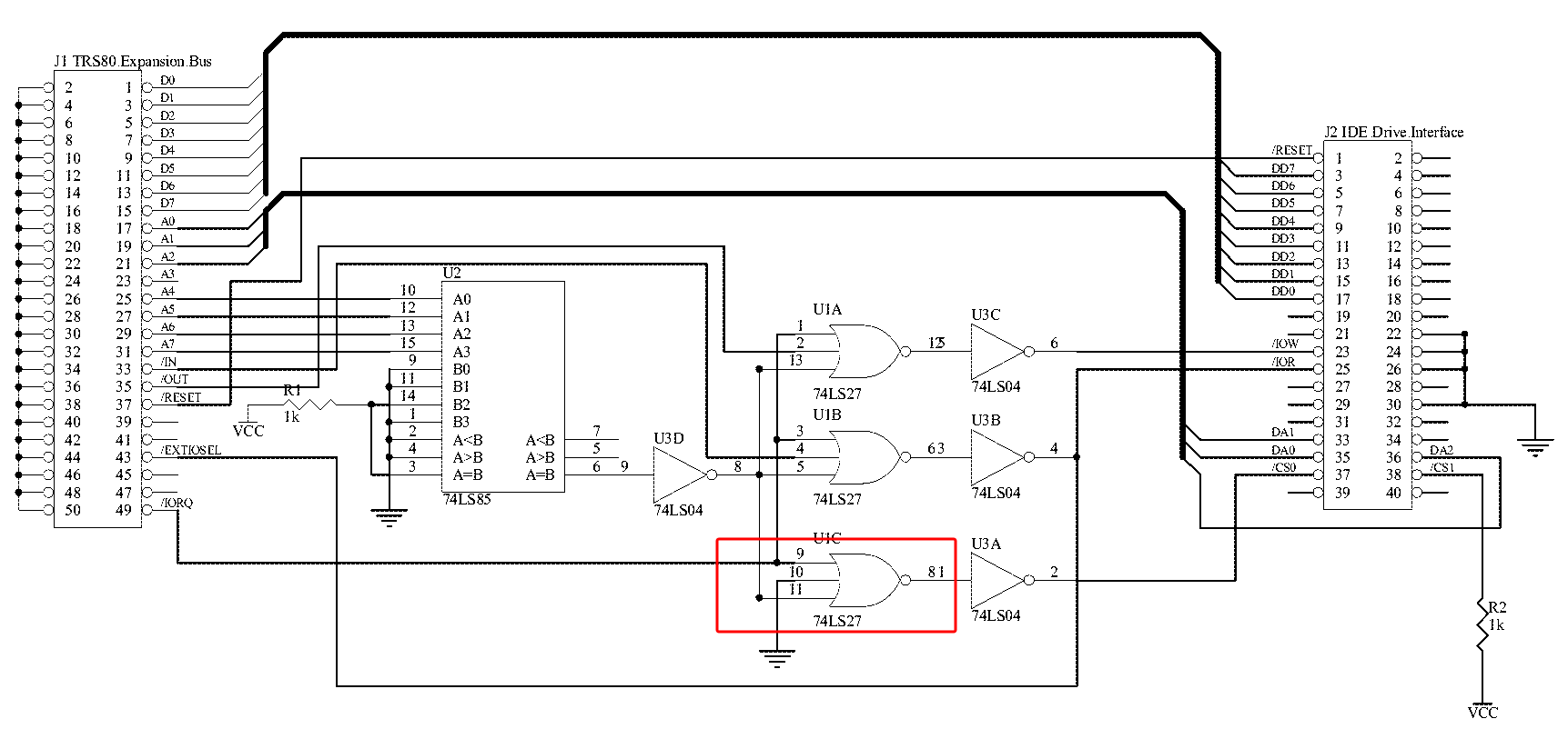
In the original design it seems that device compatibility issues might have been caused by the inclusion of IORQ in the address matching logic:

trs-80-ide-adapter-original

IORQ is asserted concurrently with IN or OUT, so the logic has a timing issue since the IDE interface expects its chip-select (i.e. address match) line to have been asserted before the read or write command.

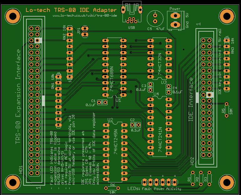
The Lo-tech design follows more the the XT-CF design, with the IDE chip-select line being driven directly from the address bus with just an LS688 comparator. Some prototyping work by vcforum member Chromedome45 soon proved the logic – so the Lo-tech TRS-80 IDE Adapter PCB design:

trs-80-ide-adapter-pcb-gerber-component-side

Lo-tech TRS-80 IDE Adapter (image generated with GerbV)

Further information on the board including bill of materials, device drivers and design files can be found on the Lo-tech TRS-80 IDE Adapter wiki page.

Availability

PCBs are available now through the lo-tech shop page.

Shugart and the Bubble

intel-bubble-logo-1981-banner

Magnetic Bubble Memory (MBM) was positioned as a major contender for computer storage in the late 1970s, even appearing in popular culture when at the center of the plot in Knight of the Phoenix.  The technology seemed to offer everything flash offers today, and is the basis of some surprising patents such as this iPod forerunner filed in 1979.

The TMS 9916 Bubble Memory Controller datasheet surmised,

…the main advantages are the low entry price versus disks…, nonvolatility…, and high-density storage… ideally suited for portable applications as well as providing memory for traditional processing systems

What Is Bubble Memory?

One_bubble_memory_track_and_loop

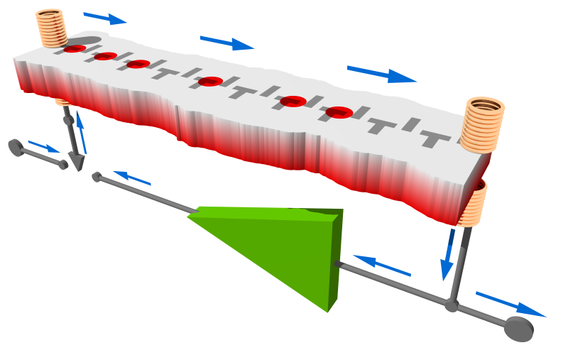
Bubble memory works like a shift register

MBM works by storing bits as cylindrical magnetic domains (the bubbles) on a film mounted within an electromagnet array, which is used to move the bubbles through the film.  Functionally, MBM is like a massive shift register – moving the bubbles results in one (stored) bit being read from one end, and a new bit being supplied at the other.

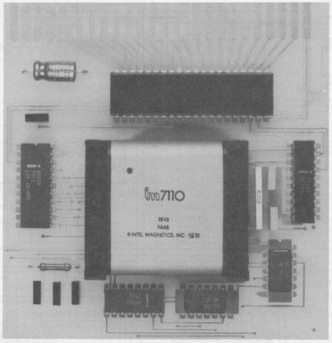
By the end of the 1970s, practically every major semiconductor manufacturer was working furiously on this technology, and of course Intel was no exception with its subsidiary ‘Intel Magnetics’.  Their 1979 Design Handbook for the Intel Magnetics One Megabit Bubble Memory is well worth a look, and includes a technical article as an appendix with some performance specifications.  The power consumption jumps out as surprisingly high for a solid-state technology.

Conner & Shugart

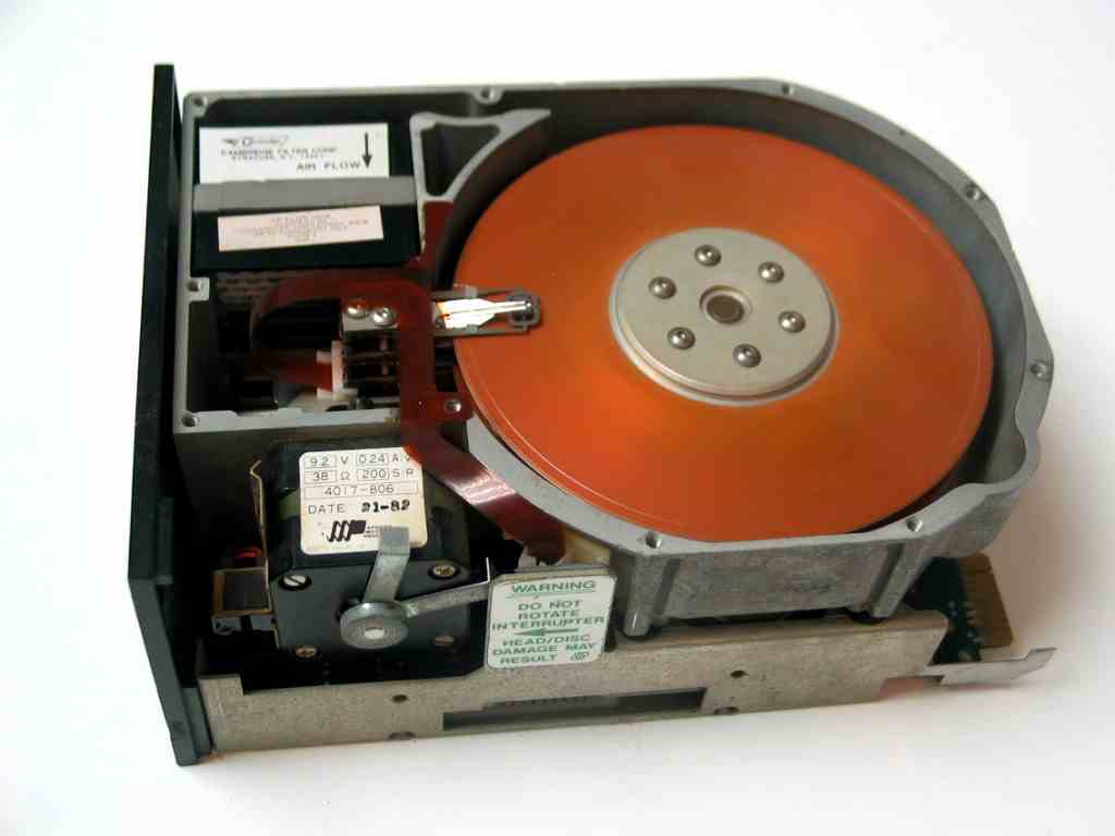
st-506-drive

ST-506 (image: fosketts.net)

Meanwhile Finis Conner and Al Shugart, having enjoyed some success as Shugart Associates with 8″ floppy and fixed disks, in 1979 formed a startup to produce 5.25″ fixed disks for the emerging personal computer industry.  Shugart Technology was born, named deliberately in the expectation of some free publicity from Shugart Associates owner Xerox.

Less than a year after incorporation, they led the storage industry with the introduction of the micro-Winchester ST-506, the first 5.25″ form factor hard drive.  With 5 MB usable capacity, it immediately provided a problem for bubble technology – and DEC (absorbed by Compaq in 1998) provided Shugart with their first major order, ST-506 drives being destined for its Rainbow PC in a deal apparently negotiated over cocktails and written on a napkin (source).

Disk vs Bubble

intel-imb-100-development-board

Intel IMB-100 Development Board

The limitations of MBM were, by 1980, becoming clear.  Whilst requiring complex controller logic similar to that of a hard disk, it was power hungry and slow in comparison: Intel’s iSBC254 bubble memory storage board needed 32W per ½MB, had a 48ms access time, burst data rate of 48KB/s and a physical volume of 50cu.in.

In contrast, the ST-506 drive boasted 10x the capacity in a package about 3x the volume, had 10x the burst data rate, and needed less than a tenth of the power per KB.  The death-knell for bubble though came when, setting the pace of capacity expansion we’ve expected since, what was by then Seagate produced the 10MB ST-412 in 1981.

Originally to be named ST-512, the drive heads were changed to thin-film type and name updated to ST-412 according to a comment on theregister, but either way the significance in vintage computing is simple: it was selected by IBM for it’s PC/XT 5160 (produced from 1983 to 1987), putting Seagate on track to become one of the most successful storage vendors today.

Meanwhile with bubble further compounded by poor yields and the need for gadolinium gallium garnet and highly toxic chemicals, by the early 1980s pretty much all efforts with bubble memory had been dropped.

ST-506/ST-412 Reliability

Even as of 2013, there’s no shortage of working ST-412 drives – I acquired one recently in an IBM PC/XT, which when powered on presumably for the first time in about 20 years booted up straight-off, loading the school accounts system it still stored without a fuss.

Running a low-level format (using the IBM XT Diagnostics disk – the formatter is hidden away in the diagnostics menu under fixed disk tests) gives a good indication of the state of a drive, and it completed without even the hint of a bad sector.  Not bad for a 28-year old drive, especially one whose “magnetic disks have a life expectancy of 5 years” according to the service manual.

Performance

The ST506 interface used by the ST-506 and ST-412 drives was derived from the SA1000 MFM floppy interface Shugart designed in the mid 1970s, and in the PC/XT it provided 5Mbps and 17 sectors per track.  Raw transfer rate is therefore about 600KB/s, but in practice much lower because an interleave was needed to allow the CPU time to collect sector data.  Running my simple disk test utility the disk does about 68KB/s with the default 6:1 interleave.

Bubble Today

Bubble memory has popped up again more recently – MIT proposed a microfluidic bubble memory in 2007 (ultimately too slow) and IBM has been working on racetrack memory for some time.  Whilst (as of 2013) it seems unlikely that bubble will be back any time soon, IBM Research suggests that Storage Class Memory (i.e. racetrack) could become mainstream if work on 3D NAND Flash fails to deliver.

Sinclair PC200 XT-CF Card

sinclair-pc200-banner

A few weeks back I wrote about the lo-tech ISA CompactFlash Adapter designed to fit the Sinclair PC200, at the request of a system owner, and based on a few ideas I already had on the drawing board at the time.

Being simple to make and cheap, the adapter has found a home in many machines besides the Sinclair already – only a couple of PCBs are left and the feedback from assemblers has been good.

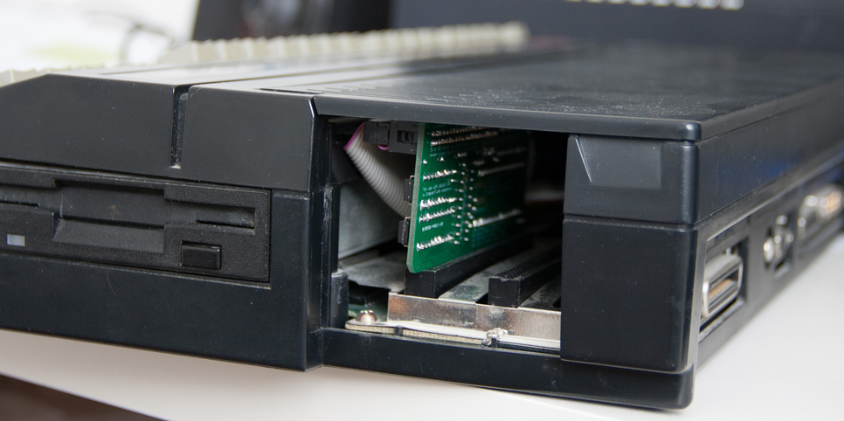
sinclair-pc200-with-lo-tech-isa-compactflash-adapter-fittedThe main challenge with the Sinclair is the available expansion slot height, which is what the small form-factor adapter was designed to solve.  Here it is fitted to the Sinclair, with the top cover fitted.

Since the Sinclair doesn’t have any spare power connectors, make use of the 4-hole power outlet on the PCB to attach a floppy-drive style power lead to power an IDE to CompactFlash adapter (alternatively the keypin on the adapter will supply 5V, if the CompactFlash adapter in use supports this).

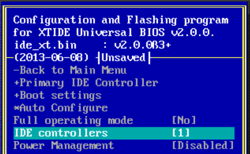
xtidecfg-ide-controllers-settingTesting, after a couple of false starts, has been successful so far.  Be sure to set ‘IDE Controllers’ to 1 (and the adapter type to XT-CF of course) when configuring the XTIDE Universal BIOS.  The BIOS can be written out using the lo-tech XT-CF flash utility.