Lo-tech PDT RollerTec Interface: Difference between revisions
No edit summary |
(→Important Information: Added link to product warnings) |
||
| (3 intermediate revisions by the same user not shown) | |||
| Line 28: | Line 28: | ||
== RaspberryPi Inferface == | == RaspberryPi Inferface == | ||
The Lo-tech PDT RollerTec RaspberryPi Interface board connects directly to the RaspberryPi 40-pin header and is based on the [[Lo-tech GPIO Interface Board rev.2|Lo-tech RaspberryPi GPIO Board]]. For this application, the board provides two opto-isolated inputs, sold-state relay outputs, DS18B20 temperature sensor, and optional DC-DC power supply (accepts 8- | |||
The Lo-tech PDT RollerTec RaspberryPi Interface board connects directly to the RaspberryPi 40-pin header and is based on the [[Lo-tech GPIO Interface Board rev.2|Lo-tech RaspberryPi GPIO Board]]. For this application, the board provides two opto-isolated inputs, sold-state relay outputs, DS18B20 temperature sensor, and optional DC-DC power supply (accepts 8-24V). | |||
<gallery widths="150px" heights="125px" perrow="4"> | <gallery widths="150px" heights="125px" perrow="4"> | ||
| Line 78: | Line 79: | ||
| IC Socket (DIP6) || - || - || DIL6 || 2 || 571-1-2199298-1 | | IC Socket (DIP6) || - || - || DIL6 || 2 || 571-1-2199298-1 | ||
|} | |} | ||
== RaspberryPi Power Supply Options == | |||
The PDT Rollertec provides an auxiliary 12V power output, but with rated output of only 20mA, this is not sufficient to power a RaspberryPi. The available capacity of the 22V output is not known. | |||
When fitted with the Lo-tech PDT RollerTec RaspberryPi Interface board, there are three power supply options: | |||
#Standard 5V DC input on the RaspberryPi itsel; | |||
#Supply a regulated 5V supply to the screw terminals where marked; or | |||
#Supply 8-24V via the screw terminals where marked. | |||
The specified DC-DC converter provides 1A output. This should be sufficient to power RaspberryPi model 2B, which is sufficient for Homebridge as at time of writing. It is recommended that later models are powered directly from the RaspberryPi system board input using an official RaspberryPi power supply rated for the model in use. | |||
== Example Implementation == | == Example Implementation == | ||
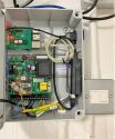
The | The system show below shows the interface kit fitted to the PDT Rollertec controller PCB mounted in an electricians style universal ABS plastic case (250x200x100mm). Push-button control can be retained by connecting both the RaspberryPi and push-to-make buttons to the respective terminals T13-15. A physical stop button should also be provided (push-to-break connected to terminals T11/T12). In this installation, the original Rollertec case has been discarded and the RaspberryPi (2B) powered using an external PoE to 5V splitter, connected to the Lo-tech interface. | ||
<gallery widths="150px" heights="125px" perrow="4"> | |||
File:Rollertec-System-Fitted.jpg | |||
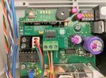
File:Rollertec-Status-Interface-Fitted.jpg | |||
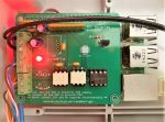
File:Rollertec-RaspberryPi-Interface-Fitted.jpg | |||
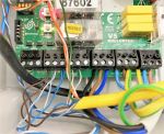
File:Rollertec-V5-Control-Board-Wiring.jpg | |||
File:Rollertec-Pushbutton-Switches.jpg | |||
</gallery> | |||
== Notes == | |||
*SD card reliability can present a challenge to long-term, always-on applications. Use of industrial-grade cards is recommended (i.e. Sandisk Industrial 8GB, Mouser order code 467-SDSDQAF3-008G-I) | |||
*Paired 433MHz keyfobs will continue to work with this kit in place, provided antenna are installed on the Rollertec controller | |||
== Important Information == | |||
*MOVING DOORS CAN CAUSE SERIOUS INJURY. NEVER OPERATE THE DOOR UNLESS YOU CAN SEE IT. | |||
*Not all doors are fitted with edge impact detectors, and even where fitted these should not be relied upon. | |||
*Use of this kit requires wiring to the Rollertec PCB, which has exposed 230V mains terminals. Ensure the board is fully isolated before opening the enclosure or making connections. If in any doubt, contact a qualified electrician. | |||
See full [[Warnings#Lo-tech PDT Rollertec Interface|Product Warnings here]]. | |||
== Resources == | == Resources == | ||
| Line 93: | Line 124: | ||
*[http://www.farnell.com/datasheets/1874889.pdf H11L1M Datasheet] | *[http://www.farnell.com/datasheets/1874889.pdf H11L1M Datasheet] | ||
*[ | *[https://www.mouser.co.uk/datasheet/2/315/AQW282EH_1_-1196636.pdf AQW282EH Solid-state Relay Datasheet] | ||
*[[RaspberryPi Boards]] | *[[RaspberryPi Boards]] | ||
Latest revision as of 20:11, 26 April 2021
The Lo-tech PDT RollerTec Interface set enables a RaspberryPi to monitor and operate the PDT RollerTec garage door controller. A HomeBridge plugin is also provided - this set brings 'Hey Siri!' to this popular garage door system.
The set consists of a small status interface (daughter board) for RollerTec PCB, and a RaspberryPi HAT style board that provides opto-isolated connectivity between the RollerTec and the RaspberryPi, as well as providing a couple of power supply options and a temperature sensor.
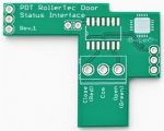
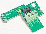
Door Status Interface
This small PCB follows the physical format on the PDT Remote Door Interface board (no longer available) and uses a 74HCT32 to drive the status signals to the RaspberryPi board.
Parts List
Mouser Parts Lists:
| Part | Value | Device | Package | Qty | Mouser |
|---|---|---|---|---|---|
| C1 | 0.1uF (100nF) | Ceramic Capacitor | Through-hole | 1 | 594-K104K15X7RF53K2 |
| HD1, HD2 | - | Header socket, 1x3 | Through-hole | 2 | 200-CES10301TS |
| HD3 | 3-way screw terminal (3.81mm) | FCI 220327-D031B01LF or Kobiconn 158-P02EK381V3-E or Multicomp MC000019 |
Through-hole | 1 | 158-P02EK381V3-E |
| IC1 | - | SN74HCT32D | SOIC-14 | 1 | 595-SN74HCT32D |
RaspberryPi Inferface
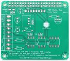
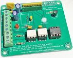
The Lo-tech PDT RollerTec RaspberryPi Interface board connects directly to the RaspberryPi 40-pin header and is based on the Lo-tech RaspberryPi GPIO Board. For this application, the board provides two opto-isolated inputs, sold-state relay outputs, DS18B20 temperature sensor, and optional DC-DC power supply (accepts 8-24V).
The board enables the Raspberry Pi to issue door commands (open and close) and monitor the door status by interpreting the PDT Rollertec status LED. This in turn enables automation, for example using HomeBridge to interface the door to Apple HomeKit, so enabling voice control of the door. A HomeBridge plugin (see links below) is provided offering this functionality.
Parts List
Mouser Parts Lists:
| Part | Value | Device | Package | Qty | Mouser |
|---|---|---|---|---|---|
| C1,C2,C3,C4 | 0.1uF (100nF) | Ceramic Capacitor | Through-hole | 1 | 594-K104K15X7RF53K2 |
| C5,C6 | 10uF | Electrolytic Capacitor | E2-5 Through-hole | 2 | 647-UVR1C100MDD |
| DC1 | Non-Isolated DC/DC Converters Non-Isolated DC/DC Converters CONV DC/DC 1A 8-42VIN 5.0VOUT | R-78C5.0-1.0 | Through-hole | 1 | 919-R-78C5.0-1.0 |
| DS1820 | Maxim Integrated DS18B20 Temperature Sensor | DS18B20 | Through-hole | 1 | 700-DS18B20+ |
| HD1, HD2, HD3 | 3-way screw terminal (3.81mm) | FCI 220327-D031B01LF or Kobiconn 158-P02EK381V3-E or Multicomp MC000019 |
Through-hole | 1 | 158-P02EK381V3-E |
| F1 | LITTELFUSE 30R135UU. POLYFUSE, PTC, 30V, RADIAL, 900MA | 30R090UU | Through-hole | 1 | 576-30R135UU |
| IC1, IC2 | H11L1M Optocoupler, Schmitt Trigger | H11L1M | DIP-6 | 2 | 512-H11L1M |
| IC3 | AQW282EH Solid State Relay - PCB Mount 60v 500mA DIP Form A Norm-Open | AQW282EH | DIP-8 | 1 | 769-AQW282EH |
| LED | 3mm LED | - | Through-hole | 1 | 645-521-9432F (red) 859-LTL-2231AT (green) |
| P1 | SOCKET, PCB, 0.1", 20+20WAY | - | Through-hole | 1 | 855-M20-7832046 |
| R1 | 270R | 125mW Carbon Film Resistor | Through-hole | 1 | 299-270-RC or 660-CFS1/4CT52R271G |
| R2 | 4k7 | 125mW Carbon Film Resistor | Through-hole | 1 | 279-CFR16J4K7 |
| R3, R4 | 1k | 125mW Carbon Film Resistor | THT | 1 | 299-1K-RC |
| RN1 | 560R Isolated | SIL-8 Resistor Network (Bournes 4608X-102 type) | THT | 1 | 652-4608X-2LF-560 |
| DIL Socket, 8-pin | - | SOCKET, VERTICAL, 1ROW, 8WAY | SIL8 | 1 | 571-215297-8 or 571-829265-8 |
| IC Socket (DIP8) | - | - | DIL8 | 1 | 571-1-2199298-2 or 649-DILB8P223TLF |
| IC Socket (DIP6) | - | - | DIL6 | 2 | 571-1-2199298-1 |
RaspberryPi Power Supply Options
The PDT Rollertec provides an auxiliary 12V power output, but with rated output of only 20mA, this is not sufficient to power a RaspberryPi. The available capacity of the 22V output is not known.
When fitted with the Lo-tech PDT RollerTec RaspberryPi Interface board, there are three power supply options:
- Standard 5V DC input on the RaspberryPi itsel;
- Supply a regulated 5V supply to the screw terminals where marked; or
- Supply 8-24V via the screw terminals where marked.
The specified DC-DC converter provides 1A output. This should be sufficient to power RaspberryPi model 2B, which is sufficient for Homebridge as at time of writing. It is recommended that later models are powered directly from the RaspberryPi system board input using an official RaspberryPi power supply rated for the model in use.
Example Implementation
The system show below shows the interface kit fitted to the PDT Rollertec controller PCB mounted in an electricians style universal ABS plastic case (250x200x100mm). Push-button control can be retained by connecting both the RaspberryPi and push-to-make buttons to the respective terminals T13-15. A physical stop button should also be provided (push-to-break connected to terminals T11/T12). In this installation, the original Rollertec case has been discarded and the RaspberryPi (2B) powered using an external PoE to 5V splitter, connected to the Lo-tech interface.
Notes
- SD card reliability can present a challenge to long-term, always-on applications. Use of industrial-grade cards is recommended (i.e. Sandisk Industrial 8GB, Mouser order code 467-SDSDQAF3-008G-I)
- Paired 433MHz keyfobs will continue to work with this kit in place, provided antenna are installed on the Rollertec controller
Important Information
- MOVING DOORS CAN CAUSE SERIOUS INJURY. NEVER OPERATE THE DOOR UNLESS YOU CAN SEE IT.
- Not all doors are fitted with edge impact detectors, and even where fitted these should not be relied upon.
- Use of this kit requires wiring to the Rollertec PCB, which has exposed 230V mains terminals. Ensure the board is fully isolated before opening the enclosure or making connections. If in any doubt, contact a qualified electrician.
See full Product Warnings here.
