Lo-tech MIF-IPC-B: Difference between revisions
m (1 revision imported) |
No edit summary |
||
| Line 7: | Line 7: | ||
A standard DB25 port provides compatibility with the original Roland cables, and is positioned such that the ISA slot bracket from an IBM parallel port card can be used. The board is based on entirely on through-hole 74xx series logic so ease of home assembly. | A standard DB25 port provides compatibility with the original Roland cables, and is positioned such that the ISA slot bracket from an IBM parallel port card can be used. The board is based on entirely on through-hole 74xx series logic so ease of home assembly. | ||
This | This board can be purchased online via [https://texelec.com/product-tag/lo-tech/ the TexElec Store]. | ||
== Specifications == | == Specifications == | ||
Latest revision as of 19:39, 12 July 2022
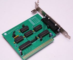
The Lo-tech MIF-IPC-B is an 8-bit ISA adapter providing connectivity for Roland MPU-401 MIDI hardware to PC, PC/XT and PC/AT class hardware.
The board features user-selectable operating modes equivalent to Roland's MIF-IPC and subsequent MIF-IPC-A boards, ensuring wide system compatibility and the prospect of running daisy-chained MPU-401 devices from a single host. The board also features user-selectable IRQ and memory address options, enabling multiple cards to be used in a single system. The board is also IBM Personal Computer XT System Board Slot 8 compatible.
A standard DB25 port provides compatibility with the original Roland cables, and is positioned such that the ISA slot bracket from an IBM parallel port card can be used. The board is based on entirely on through-hole 74xx series logic so ease of home assembly.
This board can be purchased online via the TexElec Store.
Specifications
- Connect Roland MPU-401 to PC, PC/XT and PC/AT class systems using original Roland cable
- User selectable IRQ and memory resources enable multiple cards to be used in a single system
- Original MIF-IPC mode enables daisy-chained MPU-401s
- Powered directly from ISA bus
- IBM Personal Computer XT System Board Slot 8 compatible
Design
Use of this design is provided subject to the lo-tech.co.uk Terms and Conditions.
Bill of Materials
| Part | Value | Package | Qty | Farnell | Mouser |
|---|---|---|---|---|---|
| C1..6 | 0.1uF X7R 50V | - | 6 | 594-K104K15X7RF53L2 | |
| C7 | 22uF CPOL-EUE2-5 16V | E2-5 | 1 | 647-UVR1C220MDD1TD | |
| C8 | 47uF CPOL-EUE2-5 16V | E2-5 | 1 | 647-UVR1C470MDD1TD | |
| C9 | 1uF X7R 50V | - | 1 | 810-FK14X7R1H105K | |
| IC1 | 74HCT688N | DIL20 | 1 | 382504 | 771-74HCT688N |
| IC2 | 74HCT245N | DIL20 | 1 | 9591931 | 595-SN74HCT245N |
| IC3,IC6 | 74LS08N | DIL14 | 2 | 595-SN74LS08N | |
| IC4 | 74LS33N | DIL14 | 1 | 595-SN74LS33N | |
| IC5 | 74HCT04N | DIL14 | 1 | 9591770 | 595-SN74HCT04N |
| R1 | RESISTOR, 1K, 125MW | 0204/7 | 1 | - | 270-1K-RC |
| R2,R3 | RESISTOR, 10K, 125MW | 0204/7 | 2 | 9342419 | 270-10K-RC |
| RN1 | Bournes Network 4605X-101-103LF | DIL-5 | 1 | 652-4605X-1LF-10K | |
| JP1,JP3,JP5 | Pin Header, 1x02, 2.54 | - | 3* | 571-5-146278-2 | |
| JP2 | Pin Header, 2x06, 2.54 | - | 1* | 571-826925-6 | |
| JP4 | Pin Header, 2x03, 2.54 | - | 1* | 571-826925-3 | |
| JP6 | Pin Header, 2x02, 2.54 | - | 1* | 571-826925-2 | |
| X1 | D25S33E4PA00LF | DB25 | 1 | 649-D25S33E4PA00LF | |
| DIP-14 Socket | - | - | 4 | 1101346 | 571-1-2199298-3 |
| DIP-20 Socket | - | - | 2 | 1101349 | 571-1-2199298-6 |
| - | 2-pin jumper | - | 5 | 2396301 | 806-SX1100-A |
*All pin-headers can be cut from a single, 2x15 (30-pin) header eg Mouser 538-90131-0135
Logic
ISA Bracket
The board has been designed for use with the ISA slot bracket from an IBM Personal Computer Parallel Card (1501987). The card is mounted to the bracket via the DB25 mount points.
Board Configuration
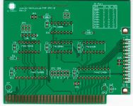
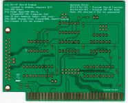
- JP1 when closed enables IBM Personal Computer XT System Board Slot 8 compatibility. This jumper should be left open except when using the card in PC/XT slot-8.
- JP2 Configures board IRQ. Close any ONE position (Roland default is IRQ2).
- JP3 defines the board operating mode:
- Open - Roland MIF-IPC-A (for PC/AT compatibility)
- Closed - Roland MIF-IPC (for PC and PC/XT compatibility)
- JP4 configures the IO port range used, between 300h and 370h (see table below). Roland default is 330h.
- JP5 configures the attachment of unused pins at DB25 socket (X1).
- Closed - Ground (per MIF-IPC-A)
- Open - Floating (per MIF-IPC)
- JP6 should be left open.
IO Port (JP4)
| IO Port Base Address | A4 | A6 | A5 |
|---|---|---|---|
| 300 | C | C | C |
| 310 | O | C | C |
| 320 | C | C | O |
| 330 | O | C | O |
| 340 | C | O | C |
| 350 | O | O | C |
| 360 | C | O | O |
| 370 | O | O | O |
Resources
- Roland Service Notes (1st edition)
- Roland Service Notes (2nd edition)
- Roland MIF-IPC Owners Manual
- Roland MIF-IPC Cable Pinout


