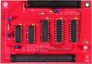
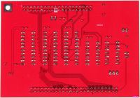
Lo-tech Yamaha C1 Music Computer IDE Adapter
The Lo-tech Yamaha C1 Music Computer IDE Adapter is a bootable storage adapter specifically for the Yamaha C1 music computer. The C1 was supplied either with dual floppy drives, or one floppy and an MFM HDD. This adapter can be used in either machine and has a special customised ROM to enable the machine to boot from the device. Any 16-bit ATA media can be attached (standard hard drives, SD-Cards via an adapter, or CompactFlash).
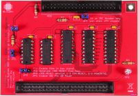
The PCB itself is a through-hole design and replaces the Yamaha MFM controller daughter board (fitted in HDD equipped models).
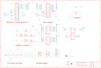
The board uses standard ATA register mapping and uses the XT-IDE Universal BIOS configured for generic 16-bit IDE controller at 1F0h. The XTIDE Universal BIOS itself (R600) has been integrated into the custom system ROM images provided below.
This PCB will be available shortly from TexElec.
Note: This PCB is currently in the testing phase.
Jumper Settings & System Resources
- ROM BIOS - integrated into Yamaha system ROM (see Downloads, below):
- IO Ports: Standard IDE port mapping, 1F0h.
Jumper Settings
| Jumper | Description | Default |
|---|---|---|
| JP1 | Enables disk in use signal generation when closed. Required to light C1 HDD activity LED. | Closed |
| JP2 | Generates IDE Reset from host when closed. | Closed |
| JP3 | Source for IDE Reset signal - 1-2 = ISA Reset, 2-3 = Powerfail | 1-2 |
| JP4 | Enable IDE Pin-20 Power | Open |
System ROM BIOS & BIOS Flashing
The board is powered by the XT-IDE Universal BIOS via integration with a custom system ROM available from the Downloads section below. The system BIOS chips cannot be programmed in-system; the two 27C256 chips (IC39 and IC40) must be removed from the system for programming (or replaced with ready-programmed chips).
The custom BIOS includes the XTIDE Universal BIOS in free space. The built-in option ROM scan has been extended into the F segment to provide initialisation.
Due to the 16-bit architecture of the machine, the ROM image is stored byte-interleaved between the two chips.
Yamaha C1 System Board Configuration
The Yamaha C1 has two DIP switch blocks - Switch block 1, on the rear panel of the machine and Switch block 2, on the system board. Use of this adapter requires that Switch Block 2 is configured as for the HDD model. Switch Block 2 is documented in the service manual on page 7:
| Switch | Function | On | Off |
|---|---|---|---|
| 1 | FDD-Selects the floppy disk or the Hard disk model. | Floppy Disk Model | Hard Disk Model |
| 2 | HDD-Selects the floppy disk or the Hard disk model. | Hard Disk Model | Floppy Disk Model |
| 3 | Bit 6 of the system configuration information. | N/A | Default (Yamaha C1) |
| 4 | Bit 7 of the system configuration information | N/A | Default (Yamaha C1) |
Installation Procedure
- Open the machine
- Remove the factory RLL controller and hard disk, if fitted
- Remove the second floppy disk drive, if fitted
- Remove the system ROM chips C39 and C40, and re-flash with the specific code
- Re-fit the system ROM chips
- Note the positions of switches on Switch Block 2
- Set on Switch Block 2: 1=off, 2=on, 3=off, 4=off
- Attach the IDE ribbon cable to the Lo-tech adapter, and set the jumpers as required
- Install the adapter and route the IDE cable as required
- Install an IDE HDD or other storage (CompactFlash etc) as required, and connect to the adapter
- Re-assemble the machine
- Power-on the machine, enter the BIOS configuration utility, and set the fixed disk type to "Not Installed"
- Boot the machine from an MS-DOS boot disk and proceed with Hard Disk configuration (FDISK, FORMAT etc)
Bill of Materials
TBC
Design
Use of this design is provided subject to the lo-tech.co.uk Terms and Conditions. The design is Copyright (c) 2019 Peacon Ltd. Assembled board images are Copyright (c) 2019, TexElec.
