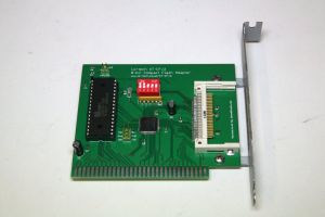
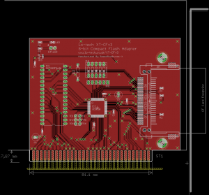
XT-CFv3
The XT-CFv3 supercedes the XT-CFv2, which had great performance and flexibility but had reliability issues when operating in the original IBM PC and PC/XT due to the 3.3V CPLD (the 3.3V part choice being driven by lack of availability of a 5V part).
As an experimental measure, the basic functionality of the XT-CF boards has been ported to the fully 7400-series based XT-CF-lite. As well as resolving reliability issues, the XT-CF-lite is easier to assemble, since it uses less fine-pitched SMT.
It now appears (as of fall, 2012) that Xilinx are re-introducing the 5V CMOS based XC9536 in 44-pin VQ44 package, and the XT-CFv3 takes advantage of this to provide most of the features of the XT-CFv2 with the ease of assembly of the XT-CF-lite, whilst also eliminating reliability issues.
General Description
The XT-CFv3 is a bootable 8-bit ISA to CompactFlash adapter for XT and AT class IBM compatible PCs.
- Replace dead MFM or RLL hard disks with cheap CompactFlash or Microdrive media
- Easy to access CompactFlash card (without opening the PC)
- Reduce system power consumption (and hence load on the PSU) by as much as 30W
- Uses the XT-IDE Universal BIOS (adapter type is 'lo-tech XT-CF')
- 32K in-system re-programmable ROM (with 24K free for any other ROM code)
- Can be used in IBM Personal Computer XT System Board Slot 8
- Reduced wait-state operation in PC/AT and newer hardware
- High-speed DMA operation; up to 500KB/s in a 4.77MHz PC/XT
Technical Resources
Design Summary
- Entirely 5V operation
- 8-bit ISA card with header for type-I or type-II CompactFlash media (operating in true-IDE mode)
- Can drive any CompactFlash compatible media, including Microdrives
- Line driver for on-card and external activity LEDs (up to 30mA)
- Design fits 100x100mm PCB layout with 10 mils spacing and 0.6mm minimum hole size
- Powered by a VQ44 Xilinx XC9536 5V CMOS CPLD (programmed on-board via JTAG pin-header)
- Low-cost DIP-32 SST39SF0x0 flash chip
- DIP switches to select configuration options
- Flash chip and CompactFlash header drive ISA data bus directly
- CPLD provides 9 outputs:
- CompactFlash: DA[0-2], CS[0-1], RESET
- ROM CS
- ISA: B8, DRQ3
Design Files
ISA Bracket
Uses Lo-tech ISA Slot Bracket Type 1.
Documentation
Construction
Bill Of Materials
Farnell Parts List:
| Part(s) | Description | Manufacturer Part No | Qty Required | Farnell Code |
|---|---|---|---|---|
| C1, C2 | CAPACITOR, RADIAL, 50V, 22UF, 20% | PANASONIC - EEUFR1H220 | 2 | 2063079 |
| C3 – C8 | CAPACITOR, 0.1UF, 10V, X7R, 0603 | KEMET C0603C104K8RACTU | 5 | 2112833 |
| CF1 | HEADER, CF2, WITH STANDOFF | 3M - N7E50-Q516RB-50 | 1 | 1267444 |
| EXT.LED | HEADER, 1ROW, 2WAY | TE CONNECTIVITY / AMP - 826629-2 | 1 | 3418285 |
| IC1 | MEMORY, FLASH, NOR, 5V, 1M, 32DIP | SST39SF010A-70-4C-PHE | 1 | 1896595 |
| IC1 Socket | CONNECTOR, DIP SOCKET | TE CONNECTIVITY / AMP - 1-390263-2 | 1 | 1654375 |
| IC2 | CMOS ISP FLASH CPLD, 9536, VQFP44 | XILINX - XC9536-15VQG44C | 1 | 1193227 |
| IC3 | LOGIC, SCHMITT TRIG, INV GATE, SOT25 | DIODES INC. - 74LVC1G14W5-7 | 1 | 1893833 |
| JTAG Header | HEADER, 2ROW, 6WAY | TE CONNECTIVITY / AMP - 826632-3 | 1 | 3418492 |
| LED | LED, 0805, LO-CUR. ORG | ROHM - SML-211DTT86K | 1 | 1685055 |
| R1 | RESISTOR, CARBON FILM, 125MW, 0R | MULTICOMP – MCRE000000 | 1 | 1700196 |
| R2 | (Do not populate) | |||
| R3, R6 | RESISTOR, 0603, 1K, 5%, 0.1W | BOURNS CR0603-JW-102GLF | 2 | 2008355 |
| R4 | RESISTOR, 0603, 5%, 5K60 | VISHAY DRALORIC CRCW06035K60JNEAIF | 1 | 1739171 |
| R5 | RESISTOR, 0603, 5%, 160R | PANASONIC – ERJ3GEYJ161V | 1 | 2059580 |
| RN1 | RESISTOR NETWORK, 10K | BOURNS - 4606X-101-103LF | 1 | 9356142 |
| SW1 | SWITCH, DIL, 5WAY | MULTICOMP - MCDS05 | 1 | 1255225 |
- Board design permits the use of a range of DIP-32 flash chips or 1, 2 or 4Mb:
- SST39SF0x0A (SST39SF010A, SST39SF020A, SST39SF040A)
- AMIC A29010
- Regardless of the chip used, the first 32KB only will be mapped into the PC address space
- Base address configuration per DIP Switch Settings
- At time of writing, BoM total is about £12 (GBP)
Assembly Notes
- Thoroughly wash the PCB before assembly with Isopropynol
- Place R3 & R4 first
- Next place CompactFlash socket and CPLD
- Next place other SMT components, then thoroughly wash the board using a toothbrush to ensure flux is removed from between SMT pins
- Next add the through-hole components, then wash again
- Before use inspect all connections with a magnifying glass to ensure there are no shorts between pins. Inspect the CompactFlash header leads as solder can sometimes flow up the leads during assembly causing a short away from the PCB itself.
Once assembled, the CPLD should be programmed and the BIOS loaded - see the DIP switch settings that follow for configuration information.
DIP Switch Settings
| Switch | Function | On | Off |
|---|---|---|---|
| 1 | ROM Enable | Enabled | Disabled |
| 2 | ROM Address | C800h | D000h |
| 3 | IO Address | 300h | 320h |
| 4 | ISA B8 / DMA Functions | ISA B8 Enabled | DMA Ch.3 Enabled |
| 5 | ISA B8 Function Type (if enabled) | PC-AT (Zero-wait-state) | PC-XT Slot 8 |
Note: The IO port address set via the DIP switches must match that set in the XTIDE Universal BIOS configuration utility
ISA B8 and DMA Function
The purpose of the ISA B8 signal depends on the system architecture:
- For the PC/XT, B8 is as a card select line to read from a card physically in the ISA slot closest to the CPU (known as slot 8), and has no function in other slots.
- In PC/AT and above, B8 is instead used to reduce wait-states.
Since the design of the PC/XT system board prevents DMA transfers from slot 8, slot 8 and DMA are mutually exclusive.
For the XT-CFv3 card to co-exist in a system with an MFM controller or other device that requires DMA Channel 3, DMA must be disabled by setting switch 4 ON.
| Card Placement | DMA function | Sw4 | Sw5 |
|---|---|---|---|
| PC/XT or clone | Enabled | OFF | OFF |
| PC/XT or clone | Disabled | ON | OFF |
| PC/XT slot-8 | Disabled | ON | OFF |
| PC/AT or newer | Disabled | ON | ON |
Compatibility and Interoperability
Use with Other Cards
- DMA channels are dedicated resources, so DMA must be disabled if another card requires DMA channel 3 (such as the Xebec Disk Cotnroller shipped with the IBM PC/XT) - see DIP Switch Settings
- The IO port address set via the DIP switches must match that set in the XTIDE Universal BIOS configuration utility
- The BIOS address can be changed via the DIP switches without changing the BIOS itself
Media Compatibility
| Media | Type | Capacity | At 3.3V | At 5V | Tester |
|---|---|---|---|---|---|
| Extreme CF Adapter | SD to Type II CF Adapter | Dependent on SD Card | - | - | - |
| Kingston CF/128 | CF | 128MB | - | - | - |
| PQI Industrial | CF | 1 GB | - | - | - |
| SanDisk Ultra II | CF | 2 GB | - | - | - |
| SanDisk Ultra (30MB/s) | CF | 4 GB | - | - | - |
| Seagate ST1 | Microdrive | 5 GB | - | - | - |
| VERBATIM 44039 | CF | 4 GB | - | - | - |
Systems Compatibility
System compatibility has determined using the DOS Disk Tester utility with a pattern test of at least 10 passes of 4MB (the default).
| System | CPU | Status | Disk Tester Version | Tester |
|---|---|---|---|---|
| IBM PC 5150 | Intel 8088 | - | 2.3 | - |
| IBM Portable PC 5155 | Intel 8088 | - | 2.3 | - |
| IBM PC/XT 5160 | NEC V20 | - | 2.3 | - |
| Chaintech 5SIM | IDT WinChip P200 | - | 2.3 | - |
Performance
Factors Affecting Performance
- System type (PC/XT vs PC/AT) and CPU type and speed
- For PC/AT and newer systems, whether the BIOS can be shadowed in system RAM or not
- The operating mode (8- or 16-bit IO-mapped, or DMA)
- The multi-sector transfer support in the media (multi-sector transfers reduce BIOS overhead, particularly in DMA transfer mode)
- ROM shadowing can offer significant gains since the flash ROM is both 8-bit and ISA bus speed limited
Sample System Measured Throughput
| System | CPU | XTIDE Build Type | Transfer Mode | Media type | Throughput |
|---|---|---|---|---|---|
| IBM PC/XT | 4.77MHz 8088 | XT | 8-bit IO-mapped | CF card supporting single-sector transfers | 170 KB/s |
| IBM PC/XT | 4.77MHz 8088 | XT | 16-bit IO-mapped | CF card supporting multi-sector transfers | 240 KB/s |
| IBM PC/XT | 4.77MHz 8088 | XT | DMA | CF card supporting multi-sector transfers | 530 KB/s |
| IBM PC/XT | 4.77MHz V20 | XT-plus | 8-bit IO-mapped | CF card supporting single-sector transfers | 351 KB/s |
| IBM PC/XT | 4.77MHz V20 | XT-plus | 16-bit IO-mapped | CF card supporting multi-sector transfers | 395 KB/s |
| Amstrad PC2086 | 6MHz 80286 | XT-plus | 16-bit IO-mapped | CF card supporting multi-sector transfers | 615 KB/s |
| Amstrad PC2086 | 6MHz 80286 | XT-plus | 16-bit IO-mapped, ZWS | CF card supporting multi-sector transfers | 811 KB/s |
| Amstrad PC2086 | 12.5MHz 80286 | XT-plus | 16-bit IO-mapped, ZWS | CF card supporting multi-sector transfers | 1,160 KB/s |

