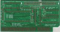
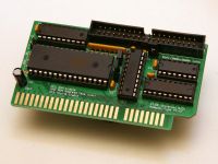
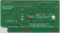
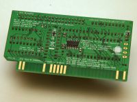
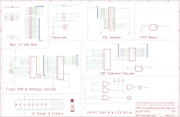
Lo-tech ISA CompactFlash Adapter revision 2b
The Lo-tech ISA CompactFlash Adapter revision 2b is a bootable storage adapter for IBM PC, PC/XT, PC/AT and compatible hardware - essentially any PC with an ISA slot. The card enables the use of:
- Standard CompactFlash cards, via any low-cost CompactFlash to IDE adapter
- SD-Cards, via an FC1306T based SD to IDE adapter
- ATA-2 compliant hard disks
For help getting this kit running, please see the Lo-tech ISA CompactFlash Adapter FAQ or Get In touch.
The BIOS ROM on the card enables the host PC to boot from storage presented by the adapter, which appears in DOS as an ordinary fixed disk (i.e. drive C, D, etc). No DOS drivers are needed.
The PCB itself is a through-hole, small form factor 8-bit ISA adapter. No slot bracket is needed, due to the small size. The design provides:
- Bootable storage adapter for 8-bit PCs
- Ease of home assembly, by use of only through-hole components for basic operation
- Small form-factor, to enable use in machines with limited expansion slot space such as the Tandy 1000HX, Sinclair PC200 and Amstrad PC-20
- IBM Personal Computer XT System Board Slot 8 compatibility (with optional SMD components mounted on rear of PCB)
- 5V supply to IDE header key-pin, for cable-less operation of CompactFlash and SD-Card adapters supporting this power option
- Selectable BIOS address - C800h or D800h
The board is programatically identical to the XT-CF-lite and uses the XT-IDE Universal BIOS, provided through an in-system re-programmable 32KB flash-based ROM. Since the BIOS is only 8KB, 24KB is available for other purposes, and is byte-programmable - the board can therefore function as a universal ROM board.
Please note that ATA and SATA hard drives cannot be used with this adapter, except ATA-2 compliant drives. The Lo-tech 8-bit IDE Adapter is compatible with standard ATA and SATA drives.
To buy this and other PCBs, please visit the lo-tech shop.
Specifications
General
- 8-bit ISA card with 40-pin IDE header for attachment to:
- IDE to CompactFlash adapter
- FC1306T based IDE to SD Card adapter
- ATA-2 compliant drives
- 5V power supply:
- to IDE header key-pin (can drive micro-drives, CompactFlash adapters and SD Card adapters without any external power connection)
- holes for attachment of peripheral power cable (for use where target host has no available peripheral power cables)
- Basic functionality is dependent only on through-hole components
- Optional SMT components provide additional functionality:
- Line driver for external activity LEDs (12mA power budget for external LED)
- IBM Personal Computer XT System Board Slot 8 compatibility
- Low-cost flash memory chip for boot ROM, with 32KB usable
- Port-mapped IO; supports both 8- and 16-bit instructions (via partial address decoding)
- Utilises XT-IDE Universal BIOS (adapter type: 'XT-CF')
- Resource requirements:
- IO ports 300-31Fh
- ROM: 32KB at C800h or D800h
Design
Use of this design is provided subject to the lo-tech.co.uk Terms and Conditions. Copyright (c) 2013,2016 Peacon Ltd (now Lo-tech Systems Limited).
Bill of Materials
Core Components
Basic functionality requires only through-hole components. JP2 must be closed, and ROM address will be fixed at C800h.
| Part | Device | Package | Qty | Farnell | Mouser |
|---|---|---|---|---|---|
| IC1, IC3 | 74HCT688N | DIP-20 | 2 | 382504 | 771-74HCT688N |
| IC2 | SST39SF010A-70-4C-PHE | DIP-32 | 1 | 1896595 | 804-39SF010A7CPHE |
| IC4 | 74HCT139N | DIP-16 | 1 | 382036 | 595-SN74HCT139N |
| IC5 | 74HCT245N | DIP-20 | 1 | 9591931 | 595-SN74HCT245N |
| RN1 | 4-element Isolated Resistor Network, 10k | SIP-8 | 1 | 9356525 | 652-4608X-2LF-10K |
| C1..5 | 0.1uF Ceramic Capacitor | C025-030X050 | 5 | 2112751 | 581-SR205E104MAR or 581-SR205C104KAR |
| C6 | 10uF Electrolytic Capacitor | E2-5 | 1 | 8767084 | 647-UVR1C100MDD |
| C8 | 2.2uF Tanalum Capacitor | - | 1 | DNP* | DNP* |
| HD1 | T821140A1S100CEU | 2x20 Pin Header, 2.54mm spacing | 1 | 2215314 | 517-30340-6002 |
| IC Socket (DIP32) | - | DIL32 | 1 | 1654375 | 571-1-2199300-2 517-4832-6000-CP |
| IC Socket (DIP20) | - | DIL20 | 3 | 1101349 | 571-1-2199298-6 649-DILB20P-223TLF |
| IC Socket (DIP16) | - | DIL16 | 1 | 1101347 | 571-1-2199298-4 649-DILB16P-223TLF |
| JP1, JP2, JP3 | - | 1x2 Pin Header | 3 | 1593411 | 855-M20-9990246 653-XG8S-0231 |
| - | - | 2-pin jumper | 2 | 2396301 | 806-SX1100-A |
- Board design permits the use of a range of DIP-32 flash chips (1, 2 or 4Mb):
- SST39SF0x0A (SST39SF010A, SST39SF020A, SST39SF040A)
- AMIC A29010
- AMIC chips appear to have been discontinued (as as Nov-13)
- Regardless of the chip used, 32KB is presented at C800h (JP2 closed) or D800h (JP2 open and R4 fitted)
- DNP = Do Not Populate
Enhanced Functionality
Additional components are required for:
- IBM Personal Computer XT System Board Slot 8 compatibility (also provides enhanced read performance for PC/AT systems)
- Device activity LED
- ROM address selection (C800h/D800h)
| Part | Device | Package | Qty | Farnell | Mouser |
|---|---|---|---|---|---|
| U1 | SN74LS33D | SOIC-14 | 1 | 1752958 | 595-SN74LS33D |
| R1, R2, R4 | RESISTOR, 10K, 125MW | 0805 | 3 | 1612522 | 71-CRCW0805J-10K-E3 |
| R3 | RESISTOR, 0.125W 1% 270R | 0805 | 1 | 1652970 | 71-CRCW0805270RJNEA |
| C7 | CAPACITOR, 0.1UF, 50V | 0805 | 1 | 1612208 | VJ0805V104MXBPW1BC |
| LED | - | 1x2 Pin Header | 1 | 1593411 | 855-M20-9990246 |
Note that when assembling SMT components, additional flux will also be needed (such as Edsyn FL22, Farnell order code 3059091).
Configuration
- JP1: ROM enable (closed = enabled)
- JP2: ROM Address Selection - closed = C800h, open (and R4 fitted) = D800h
- JP3: Slot-8/ZWS Function (closed = enabled) - requires SMT components
An external LED can be attached to the 2-pin LED header only if the optional components (on the rear of the PCB) are populated. Current limit for LED is 12mA.
The IO port address (300h - 31Fh) is fixed.
Build & Test
For additional help, please email me via the site blog.
General
This project is available in the Lo-tech store as a Bare PCB - components from the Bill of Materials above must be sourced separately for example from Farnell, Newark, Mouser, DigiKey or other electronic component supplier. Farnell and Newark part numbers are provided above for convenience.
An appropriate media adapter and storage device must be purchased separately (i.e. and IDE to CompactFlash adapter and a CompactFlash card).
A temperature controlled soldering iron is highly recommended for assembly. Tin-lead solder is generally easier to use than lead-free. A quality syringe flux is also recommended and is essential for the optional SMT parts (see SMT Soldering Notes). Before construction, the PCB should be cleaned in isopropynol.
Construction
- Find a suitable work surface with plenty of light. I find a car-cleaning sponge useful to rest the PCB on since components are held nicely in place under the PCB by the soft surface, which can also be easily turned around as a whole with components not yet soldered
- Start with the least tall components, so that they are held full in place with the solder side up
- When soldering IC sockets or ICs, ensure the notches are at the correct end as indicated by the PCB silkscreen
- If using a shrouded 40-pin header, observe correct orientation as indicated by the silkscreen. The key pin can be removed from the header with a small pair of thin-nose pliers before placement (though note that the key pin can be used to supply 5V to the required CompactFlash adapter if left in-place)
- Note the correct orientation of the polarised capacitors C6 and C8. C8 positive leg is closest to C3.
- Wash all flux residues off once complete using isopropynol (for example with a toothbrush)
- Check closely with a magnifying glass all joints. Check especially for bridges between SMT pins
BIOS Flashing (Programming)
The following assumes JP2 is closed, providing the ROM at C800h
- The board is powered by the XTIDE Universal BIOS and features a 32KB in-system re-programmable flash chip
- XTIDE Universal BIOS build R560 or newer is recommended (v2 beta 3 is much older)
- The flash chip is programmed with the Lo-tech XT-CF flash utility
- Select the appropriate ROM image:
- IDE_XT.BIN for Intel 8088 and 8086 CPUs
- IDE_XTP.BIN for NEC V20, V30, and Intel 80286 CPUs
Note: The late initialisation module in the XTIDE Universal BIOS should only be included in the BIOS build for systems that require this. The module can cause the BIOS to hang after initialisation on other systems. The BIOS build above excludes this module.
To program the board, make a DOS boot disk (utilities have been tested on MS-DOS 2.11, 3.3 and 6.22) and add the BIOS binary file and the flash utility. Install the Lo-tech ISA CompactFlash Adapter in the machine and boot from the floppy, then flash the ROM thus:
A:\>flash ide_xt.bin c800
Note that should a board containing the IDE_XTP.BIN image be moved to an Intel 8088/8086 PC, the BIOS image will cause the machine to hang during the POST. To resolve this, either re-flash the board with the IDE_XT.BIN image before moving, or disable the ROM during the POST via JP1. JP1 can be closed once the machine has booted, so enabling the ROM for programming (provided there is no other ROM at C800h).
Configuration
In addition to the board configurable options, the XTIDE Universal BIOS provides several transfer modes for Lo-tech XT-CF Boards. The Lo-tech ISA CompactFlash Adapter revision 2 supports two modes (PIO and BIU), which can be changed on-the-fly with the Lo-tech XTCFMODE Utility. The default mode, set when the BIOS is initialised (i.e. when the machine is powered-on or rebooted), is set within the BIOS via the XTIDE Universal BIOS xtidecfg.com utility.
Since the transfer mode reverts at every reboot to the mode set in the BIOS, to permanently set the transfer mode it should be configured accordingly within the BIOS. Alternatively, XTCFMODE can be included in AUTOEXEC.BAT.
For PC/AT class hardware, the use of BIU mode and enabling slot-8/ZWS function (requires optional SMT components and JP3 closed), read performance of up to 1MB/s can be achieved.
