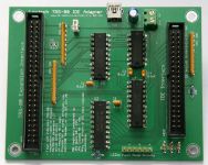
Lo-tech TRS-80 IDE Adapter
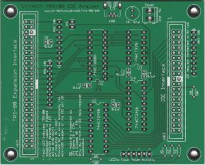
The Lo-tech TRS-80 IDE Adapter is an external IDE storage adapter for Tandy TRS-80 model 3/4/4P PCs, enabling connection of standard IDE drives (and CompactFlash cards, with an adapter). Based entirely on 7400 series logic and through-hole components, the design offers a low-cost, self-assembly storage option for these machines. The design is not currently compatible with the TRS-80 Model 1.
This PCB has been superseded by the Lo-tech TRS-80 IDE Adapter rev.2.
Technical Description
The adapter is connected to a TRS-80 host through the host expansion socket with a 50-wire ribbon cable, and provides access to the IDE device registers either:
- via IO ports 40-47h, for use with a suitable device driver; or
- via IO ports C0-C7h
The interface is fully buffered and protected against flipped cable connection.
Similar to the IBM Personal Computer XT System Board Slot 8, TRS-80 expansion cards must assert a signal to transfer data back to the host. The TRS-80 requires 33mA drive on this line (/EXTIOSEL) because of a 150-ohm pull-up resistor within the host. The Lo-tech TRS-80 IDE Adapter achieves this with 74ACT logic at U4 (U1-U3 can be LS or HCT types).
The Lo-tech TRS-80 IDE Adapter includes pull-ups on all control lines to ensure there is at least a known state on all lines at all times (and also on the unused IDE data lines).
Power Supply
Since the TRS-80 expansion port doesn't provide power, 5V DC must be supplied to the adapter. Three power supply options are provided:
- screw terminals
- mini-USB
- via the IDE header pin 20.
Note that the USB socket is only for power and should be connected to a mini-USB charger.
IDE pin 20 (the key pin) is simply connected to the Vcc (5V) line, so can be used to power the board or to supply power to an attached device (many DoM and CompactFlash adapters support pin-20 power).
Connection Cable
The TRS-80 host end has a 50-pin card-edge connector which isn't keyed. A custom cable is needed, which can be constructed by attaching a 50-pin card-edge connector (search sites like Amazon or eBay for "50 Pin IDC Card Edge Connector") to a 50-wire SCSI ribbon cable.
Because of this, there's a chance that connection could be made incorrectly (with the host end flipped). In that scenario, the card is protected by referencing the state of the expansion header pin 45 (defined as no-connection) by attaching a pull-up resistor:
- When correctly connected, the pull-up generates a high logic so enabling the 74ACT241 driving /EXTIOSEL
- When incorrectly connected, the pin will be shorted to ground at the host end, hence disabling the 74ACT241 and so protecting the board from attempting to drive a high-level into a direct short to ground. The fault LED will also then be lit (if attached).
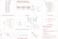
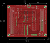
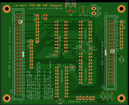
Design
Use of this design is provided subject to the lo-tech.co.uk Terms and Conditions.
Bill of Materials
| Part | Value | Device | Package | Qty | Farnell | Mouser |
|---|---|---|---|---|---|---|
| C1..C4 | 0.1uF (100nF) | Ceramic Capacitor | C025-024X044 | 4 | 1100533 | - |
| C5 | 10 - 47uF | Electrolytic Capacitor | E2-5 | 1 | 8767114 | - |
| C6 (see notes) | - | Ceramic Capacitor | - | - | - | - |
| HD1 | 2x25 Pin Boxed Header | AMPHENOL - T821150A1S100CEU | - | 1 | 2215315 | - |
| HD2 | 2x20 Pin Boxed Header | AMPHENOL - T821140A1S100CEU | - | 1 | 2215314 | - |
| JP1 | 1x2 Pin Header | AMP 826629-2 | - | 1 | 3418285 | - |
| LED | 1x6 Pin Header | AMP 826629-6 | - | 1 | 3418327 | - |
| PWR1 | 1x2 Screw Terminal | MULTICOMP MC000044 | - | 1 | 2008015 | - |
| R1..R3 (see notes) | 150R | 250mW Carbon Film Resistor | - | 3 | 2329482 | - |
| R5..R6 | 10k | 125mW Carbon Film Resistor | - | 2 | 9342419 | - |
| RN1..RN3 | 10k Bussed Resistor Network | Bournes 4609X-101-103LF | SIL9 | 3 | 9356819 | - |
| U1 | 74HCT688N | 74HCT688N | DIL20 | 1 | 381627 | - |
| U2 | 74HCT245N | 74HCT245N | DIL20 | 1 | 9591931 | - |
| U3 | 74HCT32N | 74HCT32N | DIL14 | 1 | 9591982 | - |
| U4 (see notes) | 74ACT241N | 74ACT241N | DIL20 | 1 | 1749616 | - |
| USB | Mini-USB Header | Molex 548190519 | THD | 1 | 9786465 | - |
Notes:
- U4 must be logic type ACT
- C6 can be used to increase the capacitive load on the EXTIOSEL line to increase ACT logic rise and fall time. It is not normally required and should be left unpopulated.
- The LED pin header enables the connection of LEDs each with 2-pin connectors, as with AT motherboards
- R1-R3 determine LED drive; specified values provide 30mA with forward voltage drop of 1.8V across LED
- There is no R4
- All resistors have 5mm hole spacing (for 3.5mm resistors like CFR16 series). 6.8mm resistors can be mounted upright.
- Some flux helpful when soldering the USB header
LS-DOS & CP/M Drivers
Drivers and source have been made available with the kind permission of Firebox:
